Visible to Intel only — GUID: ijr1596189558180
Ixiasoft
Fixing Other Faults in the Design Assistant Design Example
- Open the design in Quartus® Prime Pro Edition: click File > Open Project and open the top.qpf project file from the intermediate directory.
- Under Design Assistant Rule Settings, turn on Enable Design Assistant execution during compilation.
- Compile the design.
- Analyze the Design Assistant results.
The report shows fewer rule violations. The missing input delay is on an asynchronous pin and is safe.Figure 6. Design Assistant (Signoff) Results

- Observe the failing rules during the fitter plan stage. These failing rules point to high fan-out and congestion issues.
Figure 7. Fitter Plan Stage Failing Rules

- Reduce the high fan-out nets in the design (refer to Reducing High Fan-out Nets). Design Assistant can identify high fan-out nets that are candidates for duplication.
Figure 8. TMC-20601 Registers with High Immediate Fan-out
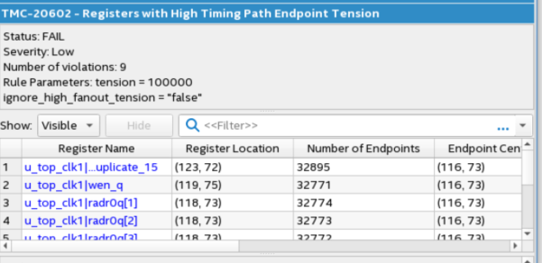
 Figure 9. TMC-20602 Registers with High Timing Path Endpoint
- Divide the memory into stripes to allow for duplication of control signals.
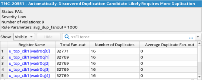
Figure 10. Memory Control SignalsTMC-20551 identifies some control signals that may need further duplication. It is the write address of a large memory.

- Explicitly duplicate registers in the RTL.
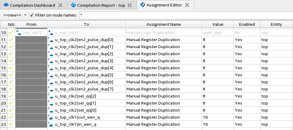
- Apply the Manual Register Duplication assignments on some of these high fan-out registers.
Figure 11. Manual Register Duplication Assignments

- Duplicate the synchronous reset signal to reduce fan-out.
- Divide the memory into stripes to allow for duplication of control signals.
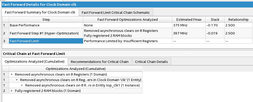
- Observe rule TMC-20204 shows the design setup-failing endpoints with retiming restrictions. Fast-forward compilation can provide recommendations.
Figure 12. Fast-forward Compilation

Refer to Hyper-Timing Restrictions for rules that indicate where hyper-retiming is limited. In the design, the timing endpoints are in M20Ks, which is a block that you cannot retime.
The final RTL removes asynchronous resets and creates a synchronous reset tree. It also adds additional pipeline stages throughout the design including the inputs to memories and on the synchronous reset tree.
- Remove initial power-up conditions.
The design has a signal that didn't reset but controls some other logic, which can lead to functional issues. Refer to the Initial Power-Up Conditions Rules for rules that detect initial conditions in the design.RES-30132 detects registers that may not be reset. Review the results to see if design reset the signal and determine if it should be reset.Figure 13. RES-30132
 Figure 14. Example of Register to Reset
Can start at any value and should be reset.

- Add a Reset Release IP.
Figure 15. Reset Release

The output of the Reset Release IP can gate internal clocks and resets to prevent race conditions. Refer to Reset Release IP for more information. The final RTL includes an instance of the reset release IP.
Refer to Reset Release IP for more information.