Visible to Intel only — GUID: cnq1487174638997
Ixiasoft
1. Overview of the Early Power Estimator for Intel® Stratix® 10 Devices
2. Setting Up the Early Power Estimator for Intel® Stratix® 10 Devices
3. Early Power Estimator for Intel® Stratix® 10 Graphical User Interface
4. Early Power Estimator Worksheets for Intel® Stratix® 10 Devices
5. Factors Affecting the Accuracy of the Early Power Estimator
6. Document Revision History for Early Power Estimator for Intel® Stratix® 10 FPGAs User Guide
A. Measuring Static Power
4.1. Intel® Stratix® 10 EPE - Common Worksheet Elements
4.2. Intel® Stratix® 10 EPE - Main Worksheet
4.3. Intel® Stratix® 10 EPE - Logic Worksheet
4.4. Intel® Stratix® 10 EPE - RAM Worksheet
4.5. Intel® Stratix® 10 EPE - DSP Worksheet
4.6. Intel® Stratix® 10 EPE - Clock Worksheet
4.7. Intel® Stratix® 10 EPE - PLL Worksheet
4.8. Intel® Stratix® 10 EPE - I/O Worksheet
4.9. Intel® Stratix® 10 EPE - I/O-IP Worksheet
4.10. Intel® Stratix® 10 EPE - XCVR Worksheet
4.11. Intel® Stratix® 10 EPE - HPS Worksheet
4.12. Intel® Stratix® 10 EPE - HBM Worksheet
4.13. Intel® Stratix® 10 EPE - Thermal Worksheet
4.14. Intel® Stratix® 10 EPE - Report Worksheet
4.15. Intel® Stratix® 10 EPE - Intel® Enpirion® Worksheet
Visible to Intel only — GUID: cnq1487174638997
Ixiasoft
4.7. Intel® Stratix® 10 EPE - PLL Worksheet
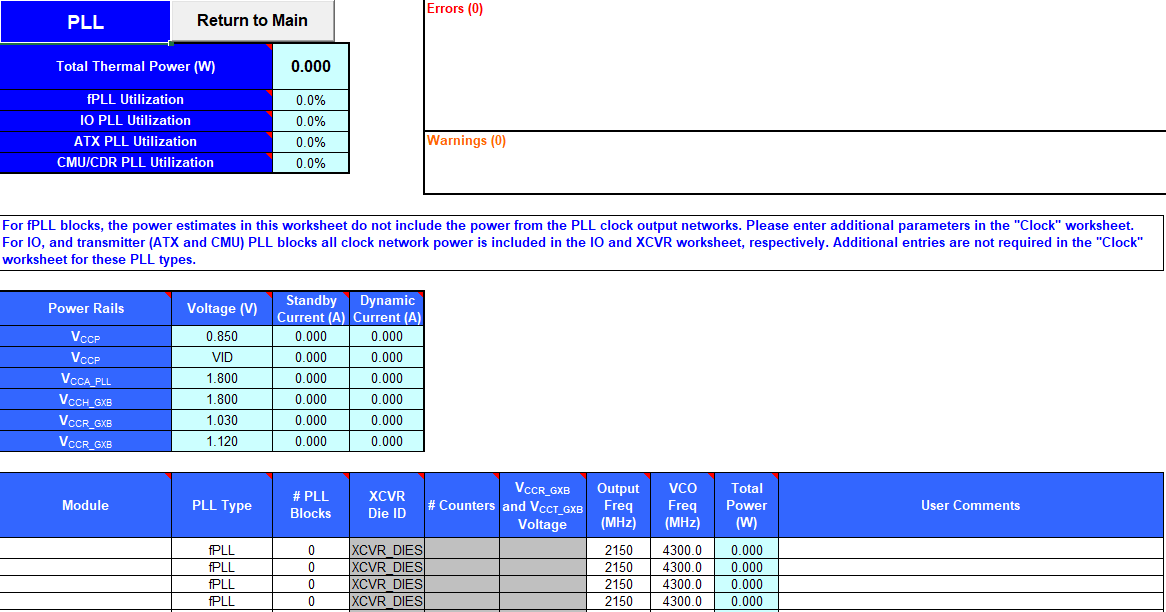
Each row in the PLL worksheet of the Early Power Estimator (EPE) for Intel® Stratix® 10 devices represents one or more PLLs in the device.
For Intel® Stratix® 10 devices, the supported PLL types are IOPLL, fPLL, ATX PLL, and CMU PLL.
Figure 13. PLL Worksheet of the Early Power Estimator


| Column Heading | Description |
|---|---|
| Module | Specify a name for the PLL in this column. This is an optional value. |
| PLL Type | Specifies the type of PLL. Intel® Stratix® 10 devices have I/O PLLs, fPLLs, CMU PLLs, and ATX PLLs. CMU PLLs and ATX PLLs are for L-tile and H-tile transceiver use exclusively. (E-tile transmitter PLLs are included in the XCVR worksheet and are not included in the PLL worksheet.) |
| # PLL Blocks | Enter the number of PLL blocks with the same combination of parameters. |
| XCVR Die ID | Specify the transceiver die on which PLLs on this row are located. This field is not applicable for I/O PLLs. |
| # Counters | Enter the number of counters of the PLL. For fPLL, this includes C counter, L counter, and feedback. This field is not applicable for ATX PLLs and CMU PLLs. |
| VCCR_GXB and VCCT_GXB Voltage | Specify the voltage of the VCCR_GXB and VCCT_GXB rails. This field is not applicable for I/O PLLs. |
| Output Freq (MHz) | Specify the output frequency for CMU and ATX PLLs. |
| VCO Freq (MHz) | Specify the internal VCO operating frequency for fPLLs and I/O PLLs. When using an fPLL as a transmitter PLL for XCVR channels, the VCO frequency has to be such that the required fPLL output frequency can be achieved using a legal value of the counter used for HSSI clock output. You can find the VCO frequency (in Hz) in the Intel® Quartus® Prime Compilation Report. In the Compilation Report, select Fitter > Plan Stage > HSSI Transmitter PLL > vco_freq for each fPLL instance. |
| Total Power (W) | Shows the total estimated power for this row (in W). |
| User Comments | Enter any comments. This is an optional entry. |
For more information about the PLLs available in Intel® Stratix® 10 devices, refer to the Intel® Stratix® 10 Clocking and PLL User Guide.