Visible to Intel only — GUID: lur1627398986386
Ixiasoft
1.1.2.1. Specify Instance-Specific Constraints in Assignment Editor
1.1.2.2. Specifying Multi-Dimensional Bus Constraints
1.1.2.3. Specify I/O Constraints in Pin Planner
1.1.2.4. Plan Interface Constraints in Interface Planner and Tile Interface Planner
1.1.2.5. Adjust Constraints with the Chip Planner
1.1.2.6. Constraining Designs with the Design Partition Planner
Visible to Intel only — GUID: lur1627398986386
Ixiasoft
2.2.2.4.3. Dynamic Reconfiguration Multi-Rate IP Tile Planning
Tile Interface Planner provides support for dynamic reconfiguration with multi-rate Intel® FPGA IP, such as the F-tile CPRI PHY Multi-Rate Intel FPGA IP.
Dynamic reconfiguration allows you to modify some features of an Intel® FPGA IP interface in real time while the FPGA remains in operation. This capability allows you to change your design to run at different data rates, and with different features for different IP "profiles."
When you generate multi-rate Intel® FPGA IP, the IP includes a .mif file specifying the base and secondary profiles that you define. Each profile contains the delta programming sequences for the dynamic reconfiguration of the IP in a linked-list format.
Once you load a design with multi-rate IP, Tile Interface Planner displays the tile location of the multi-rate IP and related building blocks within in your project. Tile Interface Planner shows the base, read-only, multi-rate IP profile as <ip_name>_0 in the Design Element hierarchy. Tile Interface Planner shows the secondary IP profiles as sec_profile_1, sec_profile_2, and so on.
Base and Secondary Profile Placement in Tile Interface Planner
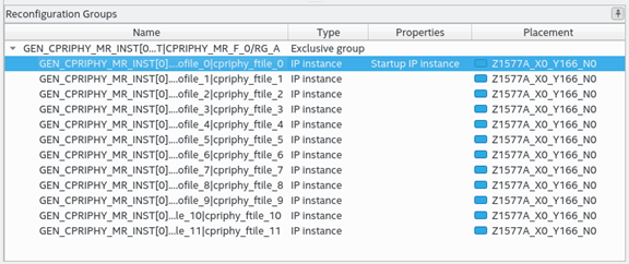
The Reconfiguration Groups view shows all IP instances that are part of a dynamic reconfiguration group, or in an multi-rate IP instance. Use this view to readily display the dynamic reconfiguration group hierarchy in the current design. The Reconfiguration Groups view shows you which IP instances in the dynamic reconfiguration group are placed, and identifies the tile placement location.
Reconfiguration Groups View (Multi-Rate IP Design)
Note: You cannot edit the multi-rate IP tile locations in the current version of Tile Interface Planner. However, you can view the multi-rate IP tile locations, and then place other IP components in relation to that location. When placing other components, Tile Interface Planner takes the multi-rate placements into account when placing other IP components.
To perform tile planning with multi-rate IP, follow these steps:
- Instantiate and elaborate a multi-rate IP component in your design, as Step 1: Instantiate IP and Run Design Analysis describes.
- Start Tile Interface Planner, as Step 2: Initialize Tile Interface Planner describes.
- Update the plan with existing assignments, as Step 3: Update Plan with Project Assignments describes.
- In Tile Interface Planner, click the Plan tab. Tile Interface Planner displays the read-only, numbered, multi-rate IP profiles in the Design Element hierarchy. The Placement column is grayed, indicating that the multi-rate IP placement is not editable in the current version of Tile Interface Planner.
Figure 36. Dynamic Reconfiguration Profiles in Tile Interface Planner
- Expand the multi-rate IP's "bb_" subfolders to view the multi-rate IP's building blocks for the dynamic reconfiguration profile.
Figure 37. IP Building Blocks for Multi-Rate Profile
- Place other IP components in relation to that location, as Placing IP Components describes. Tile Interface Planner takes the multi-rate placements into account when placing other IP components. You can explore the IP building block placement for each IP instance. Selecting the IP instance in the DR view, selects the same instance in the Design Tree view, exposing the lower-level IP building block placement.
Figure 38. Placing Other IP Components