Visible to Intel only — GUID: veq1654207944474
Ixiasoft
2.2.1.1. Common Port Mux Interface
2.2.1.2. Common Port Demux Interface
2.2.1.3. Controlled Port Mux Interface
2.2.1.4. Controlled Port Demux Interface
2.2.1.5. Uncontrolled Port RX Interface
2.2.1.6. Uncontrolled Port TX Interface
2.2.1.7. Crypto RX Interface
2.2.1.8. Crypto TX Interface
2.2.1.9. Management Interface
2.2.1.10. Decrypt Port Mux Management Interface
2.2.1.11. Decrypt Port Demux Management Interface
2.2.1.12. Encrypt Port Mux Management Interface
2.2.1.13. Encrypt Port Demux Management Interface
2.2.1.14. Crypto IP Management Bus
2.2.2.1. Common Port Mux Interface Waveform
2.2.2.2. Common Port Demux Interface Waveform
2.2.2.3. Controlled Port Mux Interface Waveform
2.2.2.4. Controlled Port Demux Interface Waveform
2.2.2.5. Uncontrolled Port RX Interface Waveform
2.2.2.6. Uncontrolled Port TX Interface Waveform
2.2.2.7. Crypto RX Waveform
2.2.2.8. Crypto TX Waveform
2.2.2.9. MACsec Management Interface (Read)
2.2.2.10. MACsec Management Interface (Write)
Visible to Intel only — GUID: veq1654207944474
Ixiasoft
5. MACsec Intel® FPGA IP Example Design
The block diagram below shows the MACsec IP design example.
Figure 19. MACsec IP Design Example
The IP GUI can generate (5) individual design examples. In order to generate one of the variants below, please select the following options for your project and IP parameter settings.
| Design | Device | Number of TX Ports | Number of TX + RX Ports | User Data Width | Port Data Width | Maximum Crypto Channels |
|---|---|---|---|---|---|---|
| 1x25G | AGID019R18A2E2V | 1 | 2 | 512 | 64 | 16 |
| 2x25G | AGID019R18A2E2V | 2 | 4 | 512 | 64 | 32 |
| 4x25G | AGIC035R39A1E2V | 4 | 8 | 512 | 64 | 64 |
| 1x100G | AGIC035R39A1E2V | 1 | 2 | 512 | 256 | 16 |
| 1x200G Simplex | AGIC035R39A1E2V | 1 | 1 | 512 | 512 | 8 |
Follow the steps below to run the design example in simulation:
- Create a project using one of the above devices.
- Create a MACsec IP variant using the above parameters for the device you have selected.
- Click the Generate Example Design button. The Select Example Design Directory appears.
- Select the directory where you want the Example Design to be placed.
- Click OK. Your design example is now generated in your chosen directory.
- Navigate to the <Example Design Directory>/example_testbench/.
- Execute a proper command to kick off simulation in your supported simulator.
Note: The MACsec Design Example incorporates the Crypto ICA Hard IP. You can integrate your own soft Crypto IP by setting CRYPTO_QHIP_EN to '0', which exposes the Crypto interfaces as shown in Crypto RX Interface and Crypto TX Interface. This configuration has not yet been validated or verified.
The table below shows the steps to simulate the testbench.
| Simulator | Instructions |
|---|---|
| Synopsys* VCS* | In the command line, type: sh run_vcs.sh |
| Synopsys VCS MX | In the command line, type: sh run_vcsmx.sh Use this script when the design contains Verilog HDL and System Verilog with VHDL. |
| QuestaSim* or Questa* Intel FPGA Edition | In the command line, type: vsim -do run_vsim.do If you prefer to simulate without bringing up the GUI, type: vsim -c -do run_vsim.do |
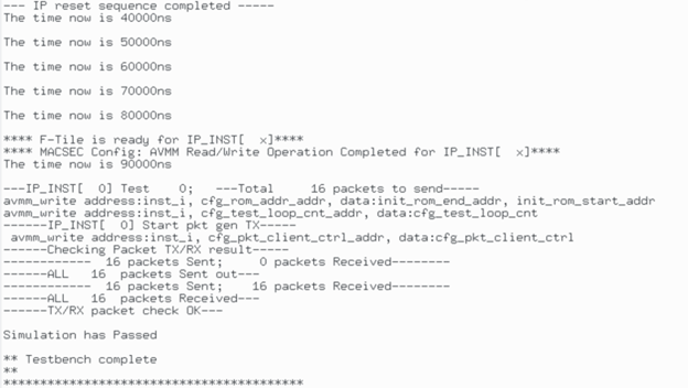
The figure below shows a sample output of the simulation.
Figure 20. Simulation Output

