Visible to Intel only — GUID: cru1439932879863
Ixiasoft
1. Nios II Custom Instruction Overview
2. Custom Instruction Hardware Interface
3. Custom Instruction Software Interface
4. Design Example: Cyclic Redundancy Check
5. Introduction to Nios® II Floating Point Custom Instructions
6. Nios II Floating Point Hardware 2 Component
7. Nios® II Floating Point Hardware (FPH1) Component
8. Document Revision History for Nios II Custom Instruction User Guide
4.1.1. Setting up the Environment for the CRC Example Design
4.1.2. Opening the Component Editor
4.1.3. Specifying the Custom Instruction Component Type
4.1.4. Displaying the Custom Instruction Block Symbol
4.1.5. Adding the CRC Custom Instruction HDL Files
4.1.6. Configuring the Custom Instruction Parameter Type
4.1.7. Setting Up the CRC Custom Instruction Interfaces
4.1.8. Configuring the Custom Instruction Signal Type
4.1.9. Saving and Adding the CRC Custom Instruction
4.1.10. Generating and Compiling the CRC Example System
6.1. Overview of the Floating Point Hardware 2 Component
6.2. Floating Point Hardware 2 IEEE 754 Compliance
6.3. IEEE 754 Exception Conditions with FPH2
6.4. Floating Point Hardware 2 Operations
6.5. Building the FPH2 Example Hardware
6.6. Building the FPH2 Example Software
6.7. FPH2 Implementation of GCC Options
6.8. Nios II FPH2 and the Newlib Library
6.9. C Macros for round(), fmins(), and fmaxs()
Visible to Intel only — GUID: cru1439932879863
Ixiasoft
4.1.5. Adding the CRC Custom Instruction HDL Files
To specify the synthesis HDL files for your custom instruction, you browse to the HDL logic definition files in the design example.
To specify the synthesis files, follow these steps:
- Click Next to display the Files tab.
- Under Synthesis Files, click Add Files.
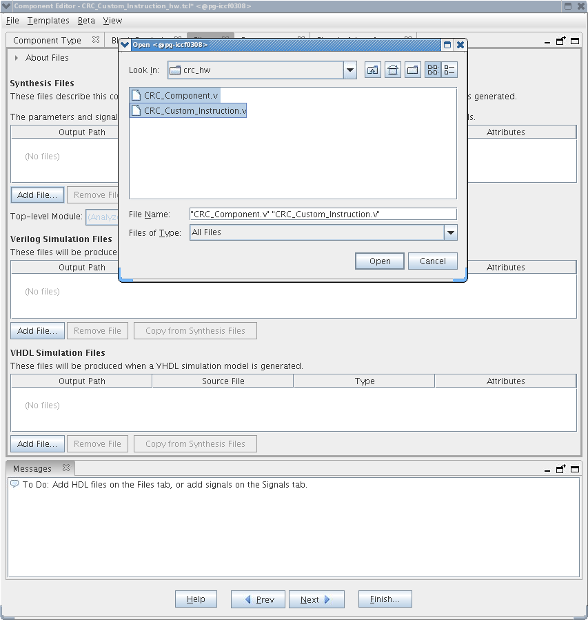
- Browse to <project_dir> /crc_hw, the location of the HDL files for this design example.
- Select the CRC_Custom_Instruction.v and CRC_Component.v files and click Open.
Figure 14. Browsing to Custom Instruction HDL Files
 Note: The Quartus® Prime Analysis and Synthesis program checks the design for errors when you add the files. Confirm that no error message appears.
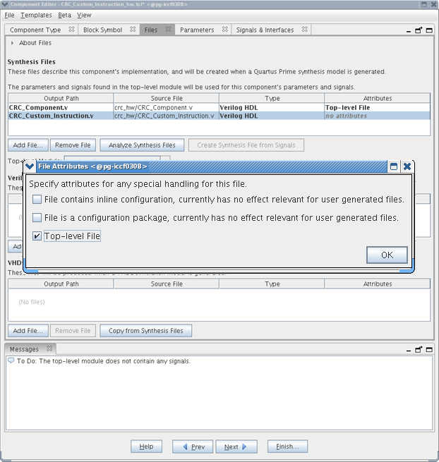
 - Open the File Attributes dialog box by double-clicking the Attributes column in the CRC_Custom_Instruction.v line.
Figure 15. File Attributes Dialog Box

- In the File Attributes dialog box, turn on the Top-level File attribute, as shown in the figure above. This attribute indicates that CRC_Custom_Instruction.v is the top-level HDL file for this custom instruction.
- Click OK.
Note: The Quartus® Prime Analysis and Synthesis program checks the design for errors when you select a top-level file. Confirm that no error message appears.
- Click Analyze Synthesis Files to synthesize the top-level file.
- To simulate the system with the ModelSim* - Intel® FPGA Edition simulator, you can add your simulation files under Verilog Simulation Files or VHDL Simulation Files in the in the Files tab.