Visible to Intel only — GUID: vat1574883297709
Ixiasoft
Visible to Intel only — GUID: vat1574883297709
Ixiasoft
2.1.3. Reset
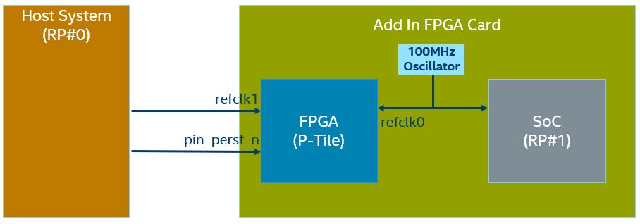
- pin_perst_n is a "power good" indicator from the associated power domain (to which P-Tile is connected). Also, it shall qualify that both the P-Tile refclk0 and refclk1 are stable. If one of the reference clocks becomes stable later, deassert pin_perst_n after this reference clock becomes stable.
- pin_perst_n assertion is required for proper Autonomous P-Tile functionality. In Autonomous mode (enabled by default), P-Tile can successfully link up upon the release of pin_perst_n regardless of the FPGA fabric configuration and will send out CRS (Configuration Retry Status) until the FPGA fabric is configured and ready.
- Avoid performing a warm reset or triggering pin_perst_n during a functional-level reset or before the functional-level reset completion. Otherwise, the PCIe link may get stuck in reset after the warm reset and cannot recover until cold reset is initiated.
- The minimum interval time required between a deassertion of pin_perst_n and the next assertion of pin_perst_n is 50us.
- Usage of the p<n>_pld_clrpcs_n_i to perform a warm reset to one of the active cores must happen only after the deassertion (i.e. high) of the corresponding p<n>_reset_status_n port. As an example, in the x8x8 configuration, in order to trigger an independent warm reset operation on p0_pld_clrpcs_n_i, the p0_reset_status_n signal must be deasserted (i.e. high). A similar constraint applies to p<n>_pld_clrphy_n_i.
The following is an example where a single PERST# (pin_perst_n) is driven with independent refclk0 and refclk1. In this example, the add-in card (FPGA and Soc) is powered up first. P-Tile refclk0 is fed by the on-board free-running oscillator. P-Tile refclk1 driven by the Host becomes stable later. Hence, the PERST# is connected to the Host.

P-tile also allows for the implementation of two independent PERST#. For more details, refer to Bifurcated Endpoint Support for Independent Warm Resets .