Visible to Intel only — GUID: koz1567042484837
Ixiasoft
Visible to Intel only — GUID: koz1567042484837
Ixiasoft
E.3. Integrate Avery BFMs (Root Complex)
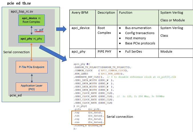
P-Tile supports serial mode connection only. The Avery Root Complex must instantiate a standalone BFM PHY to interface with the P-Tile PCIe Hard IP. The Avery BFM replaces the default Root Port BFM (dut_pcie_tb) in the P-Tile PCIe PIO example design testbench. The following diagram is a new top-level testbench, pcie_ed_tb.sv, that includes the Avery BFM.

To include the Avery BFM, use the pcie_ed_tb.sv provided in the .zip file that you download or modify the example design top-level testbench as follows:
- Open the example design top-level testbench file <example design folder>/pcie_ed_tb/pcie_ed_tb/sim/pcie_ed_tb.v.
- Import Avery BFM packages by adding the following lines below the `timescale statement:
- import avery_pkg::*;
- import apci_pkg::*;
- import apci_pkg_test::*;
- `include "apci_defines.svh"
- Include the Avery BFM by adding the following line above the example design Root Port BFM (dut_pcie_tb).
- `include "./../../apci_top_rc.sv"
- Comment out the example design Root Port BFM (dut_pcie_tb).
- Save the file and rename it to pcie_ed_tb.sv.
- Open <example design folder>/pcie_ed_tb/pcie_ed_tb/sim/common/vcs_files.tcl. Find and replace pcie_ed_tb.v with pcie_ed_tb.sv.
For details, refer to apci_top_rc.sv, pcie_ed_tb.sv, and vcs_files.tcl files available in the .zip file that you download.