Visible to Intel only — GUID: sgs1654715315841
Ixiasoft
1. Three-phase Boost Bidirectional AC/DC Converter for Electric Vehicle (EV) Charging Design Example Overview
2. Downloading and Installing the Design Example
3. Model Description
4. FPGA Resource Use Comparison
5. Locating Top-level VHDL Wrapper
6. Generating HDL Code with MATLAB and HDL Coder
7. Simulink Simulation Results
8. Document Revision History for AN 973: Three-phase Boost Bidirectional AC/DC Converter for EV Charging
Visible to Intel only — GUID: sgs1654715315841
Ixiasoft
3.2.1.2. Phase-locked Loop (PLL)
The Phase-locked Loop (PLL) block is required to assert that the phases of the generated current references are synchronous with the power grid. The rotating angle wt, an output of the PLL, is the same DQ frame rotation angle. The resulting rotation angle is used as feedback to calculate the angle wt for another DQ transform.
Note: The quadrature component of the voltage Vq is controlled to a value of 0. When Vq = 0, the PLL locks, which means that the references are fully synchronized with the grid.
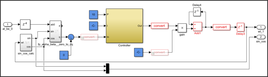
To achieve a faster lock, the PI controller within the PLL uses high values of Kp and Ki . For this implementation, Kp = 10 and Ki = 100000 Ts (Ts = 50 ns).
The following figure shows the final implementation of the PLL using Simulink blocks in the discrete-time domain for FPGA HDL coder generation:
Figure 14. Phase-locked Loop Block for Grid Synchronization