Visible to Intel only — GUID: xid1637117291484
Ixiasoft
1.3. Simulating the Design
Figure 5. Simulating the Design flow
To run example design simulation, follow these steps:
- Generate the necessary simulation setup files.
- Using GUI method:
- Open the Intel® Quartus® Prime Project in Intel® Quartus® Prime directory.
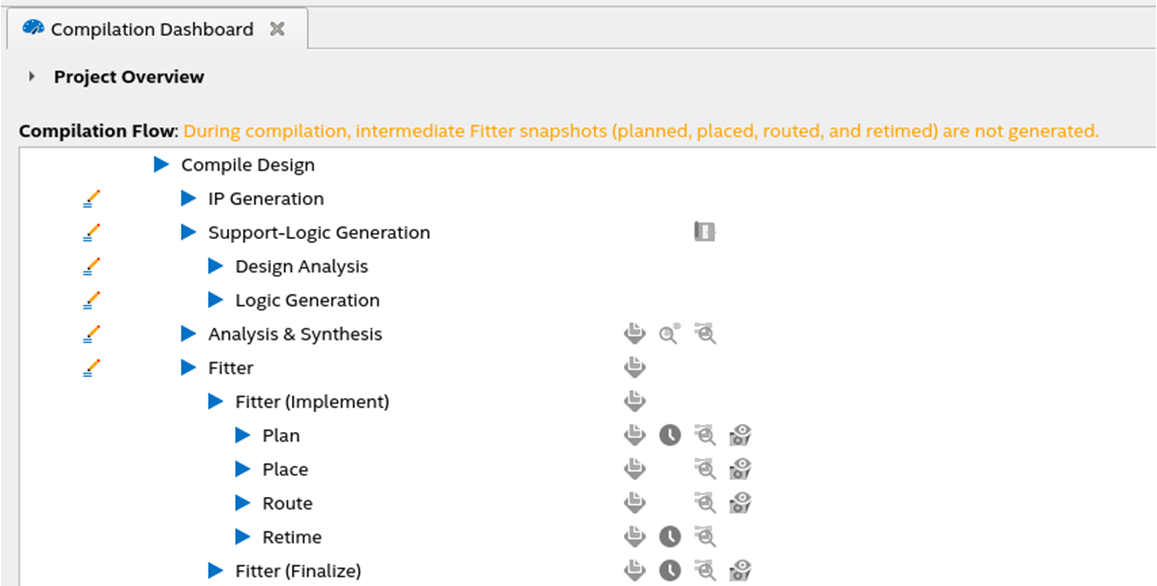
- Run Support-Logic Generation to generate the transceiver RTL files.
Figure 6. Support-Logic Generation in Compilation Dashboard

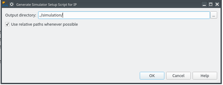
- To generate the simulation setup files, click Tools > Generate Simulator Setup Script for IP....
- Set the output directory to .../simulation.
Figure 7. Generating Simulation Setup File Using GUI


- Using command-line:
- Open a command-line terminal.
- Make sure your environment variable (QUARTUS_ROOTDIR) points to the bin/bin64 in your Intel® Quartus® Prime installation directory
- Change the current directory to the generated simulation folder in your terminal.
- Run this command source sim_setup_gen.sh.
- Using GUI method:
- Go to simulation folder.
- Go to the desired simulator folder and run the simulation script:
- ModelSim* SE or QuestaSim* FE: Bring up the simulator GUI, change directory to mentor folder and type do mentor.do
- VCS* : Go to synopsys/vcs folder and type source vcs_sim.sh.
- VCS* MX : Go to synopsys/vcsmx folder and type source vcsmx_sim.sh
- Xcelium* : Go to xcelium folder and type source xcelium_sim.sh
- A successful simulation ends with the following message:
