Visible to Intel only — GUID: wog1633599755845
Ixiasoft
Setting Up the DC-DC Converter Design Example
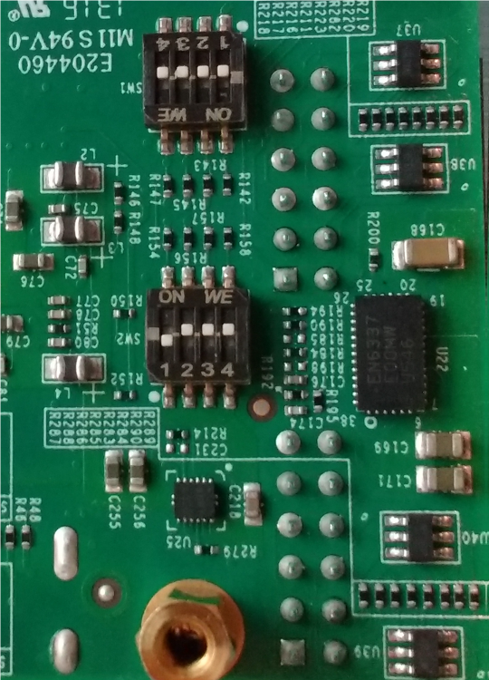
- Set DIP SW2 on the Intel MAX 10 FPGA Development Board to OFF-ON-ON-ON.
Figure 1. DIP SW2 setting

- Connect a USB cable from the USB connector J12 on the development board to your computer.
- After completing compile, click Tools > Programmer
- Click Tools > SignalTap II Logic Analyzer.
- In the SignalTap II Logic Analyzer window, in the top right corner, click Setup to select USB-Blaster II
- In the SignalTap II Logic Analyzer window, on the bottom left corner, select the data tab, then click on the top left.
Figure 2. SignalTap II Window
