Visible to Intel only — GUID: aqv1583605772424
Ixiasoft
1. Answers to Top FAQs
2. Overview of the Intel® FPGA Power and Thermal Calculator
3. Estimating Power Consumption with the Intel® FPGA Power and Thermal Calculator
4. Intel® FPGA Power and Thermal Calculator Graphical User Interface
5. Intel® FPGA Power and Thermal Calculator Pages
6. Factors Affecting the Accuracy of the Intel® FPGA PTC
7. Intel® FPGA Power and Thermal Calculator User Guide Archive
8. Document Revision History for the Intel® FPGA Power and Thermal Calculator User Guide
A. Measuring Static Power
5.1. Intel® FPGA PTC - Power Summary/Navigation
5.2. Intel® FPGA PTC - Common Page Elements
5.3. Intel® FPGA PTC - Main Page
5.4. Intel® FPGA PTC - Logic Page
5.5. Intel® FPGA PTC - RAM Page
5.6. Intel® FPGA PTC - DSP Page
5.7. Intel® FPGA PTC - Clock Page
5.8. Intel® FPGA PTC - PLL Page
5.9. Intel® FPGA PTC - I/O Page
5.10. Intel® FPGA PTC - Transceiver Page
5.11. Intel® FPGA PTC - HPS Page
5.12. Intel® FPGA PTC - Crypto Page
5.13. Intel FPGA PTC - NOC Page
5.14. Intel® FPGA PTC - HBM Page
5.15. Intel® FPGA PTC - Thermal Page
5.16. Intel® FPGA PTC - Report Page
Visible to Intel only — GUID: aqv1583605772424
Ixiasoft
5.14. Intel® FPGA PTC - HBM Page
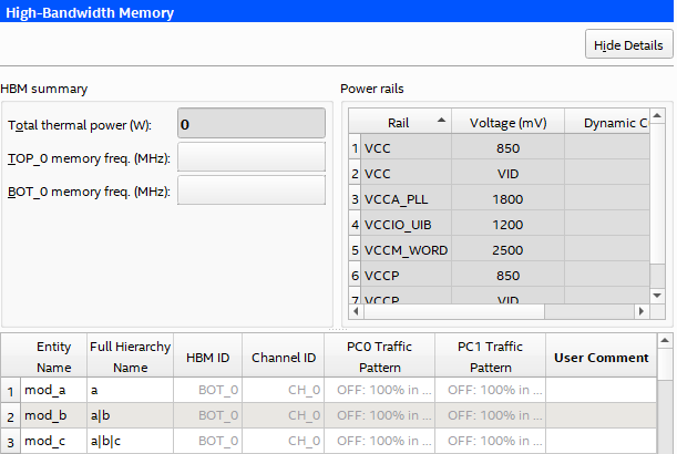
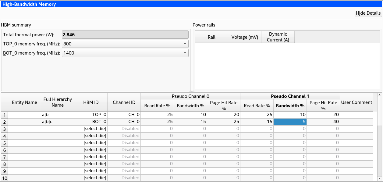
The HBM data entry page of the Intel® FPGA Power and Thermal Calculator (PTC) shows the power information pertaining to high-bandwidth memory (HBM). This page is available for Intel Agilex® 7 M-series and Intel® Stratix® 10 devices only.
| Column Heading | Description | |
|---|---|---|
| Entity Name | A user-editable field to name each entity of the design. | |
| Full Hierarchy Name | Specify the hierarchical path relevant to this entry. This is an optional entry. When entering levels of hierarchy, the pipe character (|) denotes a level of hierarchy. | |
| HBM ID | Select the top or bottom HBM stack in devices that include multiple stacks. | |
| Channel ID | Selects a particular die in the stack. | |
| PC0 Traffic Pattern | Select the traffic pattern that most closely matches your application. (PC0 and PC1 refer to the two pseudo-channels that each physical channel [0-7] is divided into; you can select different traffic patterns for each pseudo-channel.) Intel Stratix 10 devices only. | |
| PC1 Traffic Pattern | Select the traffic pattern that most closely matches your application. (PC0 and PC1 refer to the two pseudo-channels that each physical channel [0-7] is divided into; you can select different traffic patterns for each pseudo-channel.) Intel Stratix 10 devices only. | |
| Pseudo channel 0 | Read Rate % | Select to most closely match your application. Intel Agilex® 7 M-series devices only. |
| Bandwidth % | ||
| Page Hit Rate % | ||
| Pseudo channel 1 | Read Rate % | Select to most closely match your application. Intel Agilex® 7 M-series devices only. |
| Bandwidth % | ||
| Page Hit Rate % | ||
| User Comment | User Comment field. |
Figure 45. HBM Page of the Intel® FPGA PTC ( Intel® Stratix® 10 Devices)


Figure 46. HBM Page of the Intel® FPGA PTC (Intel Agilex® 7 M-series Devices)

