Visible to Intel only — GUID: jhd1530511876168
Ixiasoft
3.2.2.1. Sequencer State Machine Tab
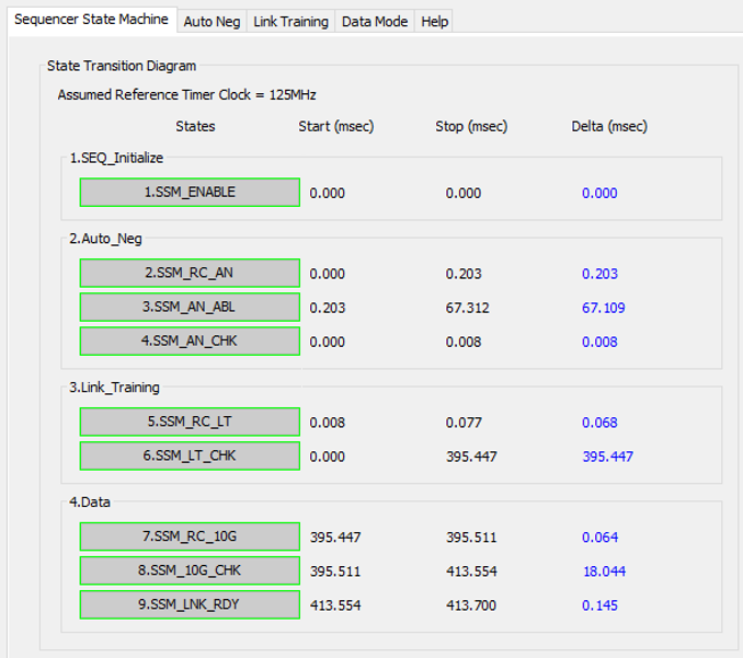
The Sequencer State Machine (SSM) tab shows the flow of sequencer state machine states that the device goes through in the specific Signal Tap capture for the selected Ethernet IP core.
Figure 7. Example of Sequencer State Machine Tab GUI

Note: SSM State names in below image is for 10GBASE-KR PHY Intel® Stratix® 10 FPGA IP core. Based on the Ethernet IP, these state names may vary. Refer to Table 4 for details on state names specific to the IP.

| Parameter | Description |
|---|---|
| Assumed Reference Timer Clock | Shows the assumed value of the clock frequency driving the reference timer. Ensure that the value of this clock is the same as the clock frequency configured in the Platform Designer window of the selected Ethernet IP core.
Note: If the assumed value of the clock frequency does not match the clock frequency in Platform Designer window of the selected IP core, the timer values displayed in Link Analysis GUI will be incorrect. For example, the Timer values reported in Start, Stop and Delta columns in the Sequencer State machine tab would be incorrect.
|
| States | Shows the flow of SSM states (from SEQ_Initialize to Data modes) that the device goes through in a specific capture. A successful state completion is highlighted in green whereas a state completion failure is highlighted in red. |
| Start | Timestamp for start time. Shows the reference timer value (in millisecond) corresponding to a specific state of SSM started. |
| Stop | Timestamp for stop time. Shows the reference timer value (in millisecond) corresponding to a specific state of SSM finished. |
| Delta | Timestamp for delta time. Shows the total time spent (in millisecond) on a specific state of SSM. |