A newer version of this document is available. Customers should click here to go to the newest version.
1. Overview
2. Getting Started
3. F-Tile Ethernet Intel® FPGA Hard IP Parameters
4. Functional Description
5. Clocks
6. Resets
7. Interface Overview
8. Configuration Registers
9. Supported Modules and IPs
10. Supported Tools
11. F-Tile Ethernet Intel® FPGA Hard IP User Guide Archives
12. Document Revision History for F-Tile Ethernet Intel® FPGA Hard IP User Guide
4.2.1.1. TX Preamble, Start, and SFD Insertion
4.2.1.2. Source Address Insertion
4.2.1.3. Length/Type Field Processing
4.2.1.4. Frame Padding
4.2.1.5. Frame Check Sequence (CRC-32) Insertion
4.2.1.6. Inter-Packet Gap Generation and Insertion
4.2.1.7. TX Packing Logic
TX Packing Logic Features
TX MAC Segmented Client Interface with Disabled TX Packing
4.4.1. Features
4.4.2. PTP Timestamp Accuracy
4.4.3. PTP Client Flow
4.4.4. RX Virtual Lane Offset Calculation for No FEC Variants
4.4.5. Virtual Lane Order and Offset Values
4.4.6. UI Adjustment
4.4.7. Reference Time Interval
4.4.8. Minimum and Maximum Reference Time (TAM) Interval for UI Measurement (Hardware)
4.4.9. UI Value and PMA Delay
4.4.10. Routing Delay Adjustment for Advanced Timestamp Accuracy Mode
5.1. Clock Connections in Single Instance Operation
5.2. Clock Connections in Multiple Instance Operation
5.3. Clock Connections in MAC Asynchronous FIFO Operation
5.4. Clock Connections in PTP-Based Synchronous and Asynchronous Operation
5.5. Clock Connections in Synchronous Ethernet Operation
5.6. Custom Cadence
7.1. Status Interface
7.2. TX MAC Avalon ST Client Interface
7.3. RX MAC Avalon ST Aligned Client Interface
7.4. TX MAC Segmented Client Interface
7.5. RX MAC Segmented Client Interface
7.6. MAC Flow Control Interface
7.7. PCS Mode TX Interface
7.8. PCS Mode RX Interface
7.9. FlexE and OTN Mode TX Interface
7.10. FlexE and OTN Mode RX Interface
7.11. Custom Rate Interface
7.12. Deterministic Latency Interface
7.13. Reconfiguration Interfaces
7.14. Precision Time Protocol Interface
7.2.1. TX MAC Avalon ST Client Interface with Disabled Preamble Passthrough
7.2.2. TX MAC Avalon ST Client Interface with Enabled Preamble Passthrough
7.2.3. Using MAC Avalon ST skip_crc Signal to Control Source Address, PAD, and CRC Insertion
7.2.4. Using MAC Avalon ST i_tx_error Signal to Mark Packets Invalid
7.4.1. TX MAC Segmented Client Interface with Disabled Preamble Passthrough
7.4.2. TX MAC Segmented Client Interface with Enabled Preamble Passthrough
7.4.3. Using MAC Segmented skip_crc Signal to Control Source Address, PAD, and CRC Insertion
7.4.4. Using MAC Segmented i_tx_mac_error to Mark Packets Invalid
4.2.1.7. TX Packing Logic
Attention: To achieve the maximum throughput when using the TX MAC segmented interface, the input packets must be packed tightly, leaving no idle segments in between.
TX Packing Logic Features
The F-Tile Ethernet Intel® FPGA Hard IP TX packing for transmit direction can be implemented in MAC segmented mode. This feature is implemented in soft logic.
-
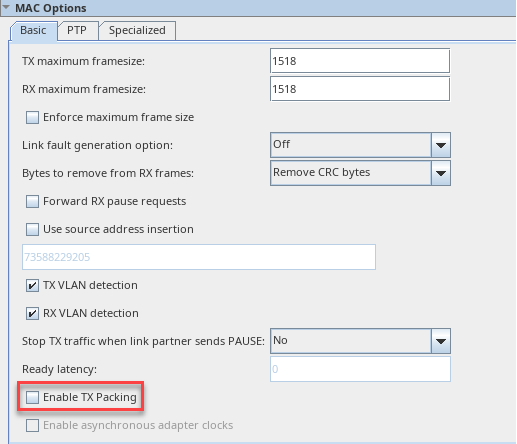
Figure 6. Enable TX Packing IP Parameter Editor
 Note: Enable TX packing feature is not available when PTP is turned on.
 - TX packing in MAC segmented mode is implemented for all rates ranging from 40G to 400G (MAC segmented interface width of 128b and above) when PTP is NOT enabled. As a result of this new logic, IP resource utilization will increase by:
- 205 ALMs for 40GE/50GE
- 791 ALMs for 100GE
- 2583 ALMs for 200GE
- 7281 ALMs for 400GE
- The TX packing logic adds an additional ~30 cycles of i_clk_tx latency.
- The TX Packing feature is disabled by default to ensure backward compatibility with the previous IP version. If you do not want to run the IP at full traffic throughput, use the disable option for lower IP utilization and latency. The maximum TX MAC throughput is reduced when sending unpacked data with idle segments in between packets while TX packing is disabled.
- When unpacked data is generated on the TX MAC segmented interface, the TX packing enabled IP to meet close to 100% line rate of all traffic with no drops or corruptions.
TX MAC Segmented Client Interface with Disabled TX Packing
To achieve close to 100% line rate without using the TX packing logic, you must implement your own packing logic on the MAC segmented interface as shown below.
The figure below depicts an example of 100GE packet data on the MAC segmented interface.
- The box on the left shows an example of loosely packed data with 2-3 idle segments in between two packets.
- The box on the right shows that data is packed with no idle segments between two packets. Pack the IPs input as shown in the right figure.
Figure 7. TX MAC Segmented Client Interface with Disabled TX Packing