A newer version of this document is available. Customers should click here to go to the newest version.
7.12. Deterministic Latency Interface
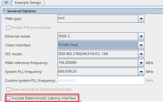
The F-Tile Ethernet Intel® FPGA Hard IP Deterministic Latency Interface ports are available when you turn on Include deterministic latency measurement interface in FlexE mode using the IP Parameter Editor.
Use the deterministic latency interface if you want to precisely measure the latency along the TX/RX datapaths. It compares the arrival time of a known digital bit (typically the start of an alignment marker) with the arrival time of an analog pulse generated at the same point.
| Signal Name |
Width | Description |
|---|---|---|
| o_tx_dl_async_pulse[n-1:0] | <n> | Asynchronous output latency pulse from TX datapath. |
| o_rx_dl_async_pulse[n-1:0] | <n> | Asynchronous output latency pulse from RX datapath. |
| i_latency_sclk[n-1:0] | <n> | Asynchronous latency calibration pulse input. |
| i_tx_dl_measure_sel[n-1:0] | <n> |
Mux select signal for the TX path.
|
| i_rx_dl_measure_sel[n-1:0] | <n> |
Mux select signal for the RX path.
|