Intel® Integrated Performance Primitives Developer Guide and Reference
A newer version of this document is available. Customers should click here to go to the newest version.
WTInv
Computes the inverse wavelet transform.
Syntax
IppStatus ippsWTInv_32f(const Ipp32f* pSrcLow, const Ipp32f* pSrcHigh, int srcLen, Ipp32f* pDst, IppsWTInvState_32f* pState);
IppStatus ippsWTInv_32f8u(const Ipp32f* pSrcLow, const Ipp32f* pSrcHigh, int srcLen, Ipp8u* pDst, IppsWTInvState_32f8u* pState);
IppStatus ippsWTInv_32f16s(const Ipp32f* pSrcLow, const Ipp32f* pSrcHigh, int srcLen, Ipp16s* pDst, IppsWTInvState_32f16s* pState);
IppStatus ippsWTInv_32f16u(const Ipp32f* pSrcLow, const Ipp32f* pSrcHigh, int srcLen, Ipp16u* pDst, IppsWTInvState_32f16u* pState);
Include Files
ipps.h
Domain Dependencies
Headers: ippcore.h, ippvm.h
Libraries: ippcore.lib, ippvm.lib
Parameters
pSrcLow |
Pointer to the vector which holds input coarse “low frequency” components. |
pSrcHigh |
Pointer to the vector which holds detail “high frequency” components. |
srcLen |
Number of elements in the vectors pSrcHigh and pSrcLow. |
pDst |
Pointer to the vector which holds the output reconstructed signal. |
pState |
Pointer to the state structure. |
Description
This function computes the inverse wavelet transform. The function transforms the “low frequency” components pSrcLow and “high frequency” components pSrcHigh into the (2*srcLen)-length destination data block pDst. The transform parameters are specified in the state structure pState.
Before using this function, you need to compute the size of the state structure and work buffer using the WTFwdGetSize_ WTInvGetSize function, and initialize the structure using WTFwdInit_ WTInvInit.
For an example on how to use this function, refer to Wavelet Transforms Example.
Application Notes
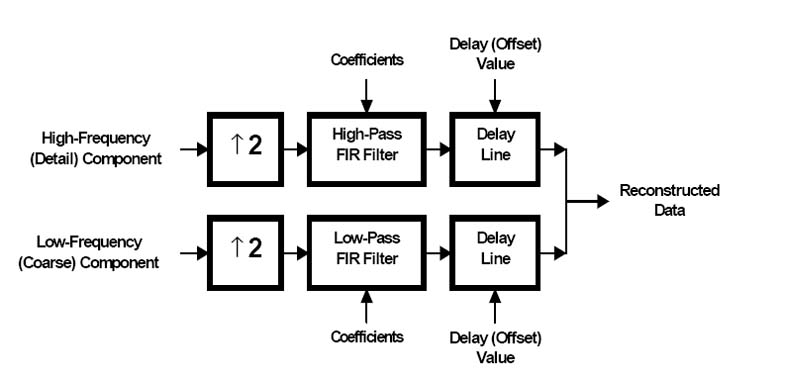
These functions are used for one level of inverse multiscale transformation which results in reconstructing the original signal from the two “low frequency” and “high frequency” components. The Figure below shows an equivalent transform algorithm. Two interpolation filters are used for signal reconstruction; their coefficients are set at the initialization stage. The inverse transform implementation, similar to forward transform implementation, contains additional delay lines needed to synchronize the group time of filter delays and delays across different levels of data reconstruction.
Input and output data block lengths. These functions are designed to reconstruct the blocks of the even length signal. The signal component length must be the input data. The length of the output block of the reconstructed signal must be double the length of each of the components.
Filter group delay synchronization. In this example consider a biorthogonal set of spline filters of length 2 and 6:
static const float recLow[2] =
{
     1.00000000e+000f,
     1.00000000e+000f
};
static const float recHigh[6] =
{
    -1.25000000e-001f,
    -1.25000000e-001f,
     1.00000000e+000f,
    -1.00000000e+000f,
     1.25000000e-001f,
     1.25000000e-001f
};
This set of filters corresponds to the set of filters considered in a similar section of the description of the forward transform function ippsWTFwd.
Unlike the case described above, this time the high-pass filter generates a delay greater by two samples compared against the low frequency filter. The two sample difference should also exist between initialization function additional delays. The following parameters of additional delays need to be selected in order to ensure the minimum total delay, offsLow = 2, offsHigh = 0. In this case the total delay is equal to the high-pass filter group delay, which at the decomposition stage is equal to two samples in the original signal time frame.
Total delay of one level of decomposition and reconstruction is equal to 4 samples, considering the decomposition stage delay.
Biorthogonal and orthogonal filter banks are distinguished by one specific peculiarity, that is, inverse transform additional delays must be uniformly even and opposite to the evenness of the decomposition delays for faultless signal reconstruction.
Multilevel reconstruction algorithms. An example of a three-level signal reconstruction algorithm is shown in Figure "Three-Level Discrete Wavelet Reconstruction". The scheme corresponds to the decomposition scheme described in the section of the description of the forward transform function ippsWTFwd. Therefore, for the inverse transform the biorthogonal set of spline filters with respective filter length of 6 and 2 is used. The lowest level filter delays are set to offsLow3 = 2, offsHigh3 = 0. The total delay at this stage of reconstruction is equal to two samples. In order to ensure an equivalent delay of the “detail” part in the middle level, the delay must be increased. Respective values of additional delays for the second level are equal to offsLow2 = 2, offsHigh2 = offsHigh3 + 2*2 = 4. A greater value of high frequency component delay needs to be selected for the last level of reconstruction, offsLow1 = -1, offsHigh1 = offsHigh2 + 2*4 = 12.
The total delay for three levels of reconstruction is equal to 12 samples. The total delay of the three-level decomposition and reconstruction cycle is equal to 24 samples.

Return Values
ippStsNoErr |
Indicates no error. |
ippStsNullPtrErr |
Indicates an error when one of the specified pointers is NULL. |
ippStsStateMatchErr |
Indicates an error when the state identifier pState is incorrect. |
ippStsSizeErr |
Indicates an error when dstLen or srcLen is less than, or equal to 0. |