Visible to Intel only — GUID: tai1705946035853
Ixiasoft
Answers to Top FAQs
1. Parameterizable Macros for Intel FPGAs Overview
2. Dual-Port Random Access Memory (RAM) Parameterizable Macros
3. FIFO Parameterizable Macros
4. I/O PLL Parameterizable Macro (ipm_iopll)
5. CDC Parameterizable Macros
6. Document Revision History for the Parameterizable Macros for Intel FPGAs User Guide
7. Parameterizable Macros for Intel FPGAs User Guide Archives
2.1.1. Simple Dual-Port RAM Parameterizable Macro Port Descriptions
2.1.2. Simple Dual-Port RAM Parameterizable Macro Parameters
2.1.3. Simple Dual-Port RAM VHDL Instantiation Template
2.1.4. Simple Dual-Port RAM Verilog Instantiation Template
2.1.5. Simple Dual-Port RAM SystemVerilog Instantiation Template
5.1. Synchronous Reset Synchronizer Parameterizable Macro (ipm_cdc_sync_rst)
5.2. Asynchronous Reset Synchronizer Parameterizable Macro (ipm_cdc_async_rst)
5.3. Synchronizer Using Single Clock Parameterizable Macro (ipm_cdc_1clk_sync)
5.4. Synchronizer Using Two Clocks Parameterizable Macro (ipm_cdc_2clks_sync)
5.5. Glitchless Clock MUX Parameterizable Macro (ipm_cdc_glitchless_clk_mux)
5.6. Bus Synchronizer Parameterizable Macro (ipm_cdc_bus_sync)
5.7. Pulse Synchronizer Parameterizable Macro (ipm_cdc_pulse_sync)
5.1.1. Synchronous Reset Synchronizer Parameterizable Macro Port Descriptions
5.1.2. Synchronous Reset Synchronizer Parameterizable Macro Parameters
5.1.3. Synchronous Reset Synchronizer VHDL Instantiation Template
5.1.4. Synchronous Reset Synchronizer Verilog Instantiation Template
5.1.5. Synchronous Reset Synchronizer SystemVerilog Instantiation Template
5.2.1. Asynchronous Reset Synchronizer Parameterizable Macro Port Descriptions
5.2.2. Asynchronous Reset Synchronizer Parameterizable Macro Parameters
5.2.3. Asynchronous Reset Synchronizer VHDL Instantiation Template
5.2.4. Asynchronous Reset Synchronizer Verilog Instantiation Template
5.2.5. Asynchronous Reset Synchronizer SystemVerilog Instantiation Template
5.3.1. Synchronizer Using Single Clock Parameterizable Macro Port Descriptions
5.3.2. Synchronizer Using Single Clock Parameterizable Macro Parameters
5.3.3. Synchronizer Using Single Clock VHDL Instantiation Template
5.3.4. Synchronizer Using Single Clock Verilog Instantiation Template
5.3.5. Synchronizer Using Single Clock SystemVerilog Instantiation Template
5.4.1. Synchronizer Using Two Clocks Parameterizable Macro Port Descriptions
5.4.2. Synchronizer Using Two Clocks Parameterizable Macro Parameters
5.4.3. Synchronizer Using Two Clocks VHDL Instantiation Template
5.4.4. Synchronizer Using Two Clocks Verilog Instantiation Template
5.4.5. Synchronizer Using Two Clocks SystemVerilog Instantiation Template
5.5.1. Glitchless Clock MUX Parameterizable Macro Port Descriptions
5.5.2. Glitchless Clock MUX Parameterizable Macro Parameters
5.5.3. Glitchless Clock MUX VHDL Instantiation Template
5.5.4. Glitchless Clock MUX Verilog Instantiation Template
5.5.5. Glitchless Clock MUX SystemVerilog Instantiation Template
Visible to Intel only — GUID: tai1705946035853
Ixiasoft
5.7. Pulse Synchronizer Parameterizable Macro (ipm_cdc_pulse_sync)
The Pulse Synchronizer parameterizable macro synchronizes a pulse in the source clock domain to the destination clock domain. A pulse of any size in the source clock domain, if initiated correctly, generates a pulse the size of a single destination clock period.
Figure 14. Pulse Synchronizer Parameterizable Macro Block Diagram
For proper operation, you must sample the input data two or more times by the destination clock. You can define the number of register stages used in the synchronizers.
This macro also requires the following minimum gap between subsequent pulse inputs:
2 *larger clock period of src_clk or dst_clk
The Quartus® Prime software measures the minimum gap between the falling edge of src_pulse to the rising edge of the next src_pulse . You must assert src_rst and dst_rst simultaneously for at least the following duration to fully reset all logic in the macro:
((NUM_STAGES +2) *dst_clk period) + (2*src_clk period)
When you assert reset, the input pulse signal should not toggle, and the output pulse signal is not valid and you can ignore the output pulse signal.
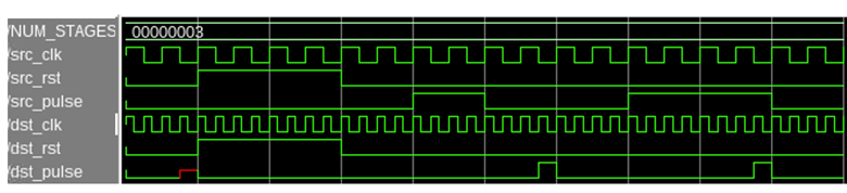
The following waveform demonstrates how to reset the macro and transfer back-to-back pulses with minimum gap between each pulse:
Figure 15. Transfer of Back to Back Pulse Timing Diagram