Visible to Intel only — GUID: sht1719421315987
Ixiasoft
2.5.2.1. Parameter Group: Global Parameters
2.5.2.2. Parameter Group: activation
2.5.2.3. Parameter Group: pe_array
2.5.2.4. Parameter Group: pool
2.5.2.5. Parameter Group: depthwise
2.5.2.6. Module: softmax
2.5.2.7. Parameter Group: dma
2.5.2.8. Parameter Group: xbar
2.5.2.9. Parameter Group: filter_scratchpad
2.5.2.10. Parameter Group: input_stream_interface
2.5.2.11. Parameter Group: output_stream_interface
2.5.2.12. Parameter Group: config_network
2.5.2.13. (Early Access) Parameter Group: layout_transform_params
Visible to Intel only — GUID: sht1719421315987
Ixiasoft
2.7.1. Input Streaming
When input streaming is configured in the IP system architecture as described in Parameter Group: input_stream_interface, the FPGA AI Suite IP accepts inputs through the AXI4-Stream signals that are exposed at the top-level instead of being memory mapped. The exposed signals are as follows:
| Signal | Source | Width | Description |
|---|---|---|---|
| ACLK | Clock | 1 | Data source clock |
| ARESETn | Reset | 1 | Data source active-low reset |
| TVALID | Data source | 1 | Input signal that indicates whether the values in TDATA are valid. |
| TREADY | FPGA AI Suite IP | 1 | Output signal that indicates whether the FPGA AI Suite IP is ready to accept data. |
| TDATA | Data source | DATA_WIDTH | Input data bus. |
Schematically, the input streaming component is constructed as follows:
Figure 8. Input Streamer Schematic View
The streamed input tensor format must be in HWC, where channels is the fastest-changing dimension. The HWC tensors are internally folded and vectorized to CHWCvec tensors that the PE array can ingest (as described in Input Feature Tensor In-Memory Format). Data also internally crosses from the source clock domain to the FPGA AI Suite IP internal clock domain.
This subset of the AXI4 streaming protocol signals implements a streaming interface where transfers take place whenever the TREADY and TVALID signals are asserted. The input streaming interface does not implement the TSTRB or TKEEP signals, which means that all data in a valid TDATA signal transfer must be valid unless it is the last transfer.
Any data beyond the boundary of the input tensor in the final transfer of an input feature that is not a multiple of DATA_WIDTH is ignored. The data stream producer is responsible for padding features, if needed, so that adjacent features to not share the same data transfer at the boundary.
The following timing example shows a 3x3x1 input tensor with monotonically increasing pixel values and DATA_WIDTH of 4 bytes. Note the padding in the third transfer.
Figure 9. Streaming Input Waveform
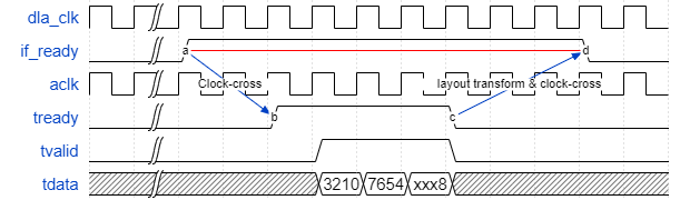
The TREADY signal is asserted by the FPGA AI Suite IP whenever the IP is ready for a new input feature and there is no back-pressuring in the system. The TREADY signal comes from the input feeder module and is first asserted once the FPGA AI Suite IP is configured. This is the FPGA AI Suite IP ‘armed’ state. Aside from potential back-pressuring during transmission, the TREADY signal is de-asserted once a complete input feature has been received and remains de-asserted until inference has completed on the current feature and the next inference has begun. The TREADY signal can also be de-asserted during a transmission if the downstream system back-pressures the inputs.
When the input streaming interface is enabled, it requires the input layout transform to be enabled and configured as described in Parameter Group: input_stream_interface. Because the layout transform configuration is graph-specific, input-streaming-enabled architectures are graph specific and run only the graph that was used to parameterize the overlay architecture.
When streaming data is received, it is converted from HWC format, where channels is the fastest-changing dimension in the memory representation, to CHWCvec format, where the input has been vectorized into Cvec-lines that can be input to the PE array.
The layout transform can be configured to either accept FP16 input data or uint8 input data that is converted internally to FP16.
The input streaming module handles clock-domain crossing from the input stream clock domain to that of the FPGA AI Suite IP and also handles width conversion from DATA_WIDTH to CVEC.