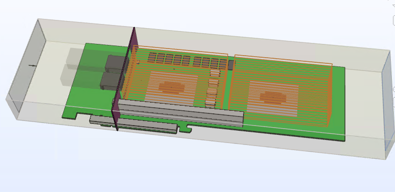
7.1. Example 2—Full Length 1 Slot PCIe with 2 FPGAs
To begin with, assume the same resource selections as in the previous example; however, the second FPGA could be reprogrammed in the field, resulting in various levels of core resource usage. Our goal is to establish the effective ambient temperature and ΨCA, so that we can determine the thermal viability of future applications just by running the Intel® FPGA Power and Thermal Calculator (PTC).

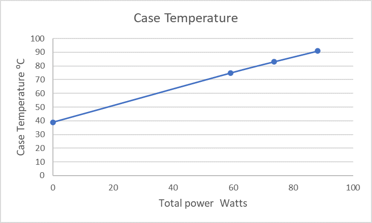
For purposes of this example, let's assume that the design targets a 35°C data center environment, and airflow over the card is 20 CFM. Using the methodology described above, we perform three sets of CFD analysis, for FPGA core die powers of 43.5 W, 58 W and 72.5 W.

The above graph shows that the effective ΨCA is 0.6°C/W and the effective ambient temperature is 40⁰C.
With the maximum TJ set to 95°C, if we were to change the ambient temperature to 40°C in the PTC, the ΨCA would become 0.66⁰C/W , indicating that we could still add more power before reaching the FPGA's effective ΨCA. In this example the core power could be increased by almost 6 watts before ΨCA reaches its limit. Alternatively, if the solution mode is set to Find a cooling solution for the Maximum junction temperature limit and TJ set to 95°C and TAMB to 40°C in the PTC, the ΨCA calculated is 0.66⁰C/W , indicating that we could still add more power before reaching the FPGA's effective ΨCA. In this example the core power could be increased by almost 6 watts before ΨCA reaches its limit.
