Intel® FPGA SDK for OpenCL™ Pro Edition: Best Practices Guide
A newer version of this document is available. Customers should click here to go to the newest version.
2.4.1.4. Reviewing Cluster Information
This view shows the following:
- Fine grained details within clusters (including instructions and dependencies of the instructions) of the generated datapath of computations.
- Linking from the instruction back to source line by clicking the instruction node.
- Various information about the instructions, such as data width, node’s schedule information in start cycle and latency are provided, if applicable.
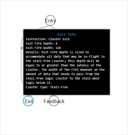
A cluster starts with an entry node and ends with an exit node. The cluster exit node has a FIFO of depth greater than or equal to the latency of the cluster to store any data in-flight. You can find the size of the cluster exit FIFO by clicking on the exit node. The cluster exit FIFO size information is also available in the block view of the System Viewer.


Besides computation nodes, when your design contains loops, you can see loop orchestration nodes and variable nodes along with their Feedback nodes. The compiler generates the loop orchestration logic for loops in your design. This logic is represented by loop orchestration nodes in the cluster view of the System Viewer. A variable node corresponds to a variable that has loop-carried dependency in your design. A variable node goes through various computation logic and finally feeds to a Feedback node that connects back to the variable node. This back edge means that the variable is passed to the next iteration after the new value is evaluated. Scan for loop-carried variables that have a long latency to the Feedback nodes as they can be the II bottlenecks. You can cross-check by referring to the Loop Analysis report for more information about the II bottleneck. The Feedback node has a FIFO to store any data in-flight for the loop and is sized to d*II where d is the dependency distance and II is the initiation interval. You can find the size of the cluster exit FIFO by clicking on the feedback node and looking at the Details pane or the pop-up box. Refer to Figure 18 for cluster exit FIFO details in the cluster view example.