Intel® Quartus® Prime Pro Edition User Guide: Programmer
ID
683039
Date
9/26/2022
Public
A newer version of this document is available. Customers should click here to go to the newest version.
1.1. Generating Primary Device Programming Files
1.2. Generating Secondary Programming Files
1.3. Enabling Bitstream Security for Intel® Stratix® 10 and Intel® Agilex™ Devices
1.4. Enabling Bitstream Encryption or Compression for Intel® Arria® 10 and Intel® Cyclone® 10 GX Devices
1.5. Generating Programming Files for Partial Reconfiguration
1.6. Generating Programming Files for Intel® FPGA Devices with Hard Processor Systems
1.7. Scripting Support
1.8. Generating Programming Files Revision History
2.1. Intel® Quartus® Prime Programmer
2.2. Programming and Configuration Modes
2.3. Basic Device Configuration Steps
2.4. Specifying the Programming Hardware Setup
2.5. Programming with Flash Loaders
2.6. Verifying the Programming File Source with Project Hash
2.7. Using PR Bitstream Security Verification ( Intel® Stratix® 10 Designs)
2.8. Stand-Alone Programmer
2.9. Programmer Settings Reference
2.10. Scripting Support
2.11. Using the Intel® Quartus® Prime Programmer Revision History
2.9.1. Device & Pin Options Dialog Box
2.9.2. More Security Options Dialog Box
2.9.3. Output Files Tab Settings (Programming File Generator)
2.9.4. Input Files Tab Settings (Programming File Generator)
2.9.5. Bitstream Co-Signing Security Settings (Programming File Generator)
2.9.6. Configuration Device Tab Settings
2.9.7. Add Partition Dialog Box (Programming File Generator)
2.9.8. Add Filesystem Dialog Box (Programming File Generator)
2.9.9. Convert Programming File Dialog Box
2.9.10. Compression and Encryption Settings (Convert Programming File)
2.9.11. SOF Data Properties Dialog Box (Convert Programming File)
2.9.12. Select Devices (Flash Loader) Dialog Box
2.3. Basic Device Configuration Steps
Basic FPGA Device Configuration over JTAG involves opening the Intel® Quartus® Prime Programmer, connecting to a device on a development kit or board, and loading the configuration SRAM Object File (.sof) into the SRAM of the FPGA. The following steps describe the basic JTAG device configuration flow:
- To run the Assembler to generate primary programming files, click Processing > Start > Start Assembler. The Compiler runs any prerequisite stages and generates programming files according to your specifications, as Generating Primary Device Programming Files describes.
- To open the Programmer, click Tools > Programmer.
- Connect the board cables. For JTAG device configuration, connect the JTAG USB cable to the board, and connect the power cable attached to the board to a power source.
- Turn on power to the board.
- In the Programmer, select JTAG for the programming Mode, as Programming and Configuration Modes describes.
- Click Hardware Setup. In the Hardware list, select connected programming hardware, as Specifying the Programming Hardware Setup describes.
Figure 25. Hardware Setup
- In the Found Devices list, select the device that matches your design and click OK.
Figure 26. Select Device
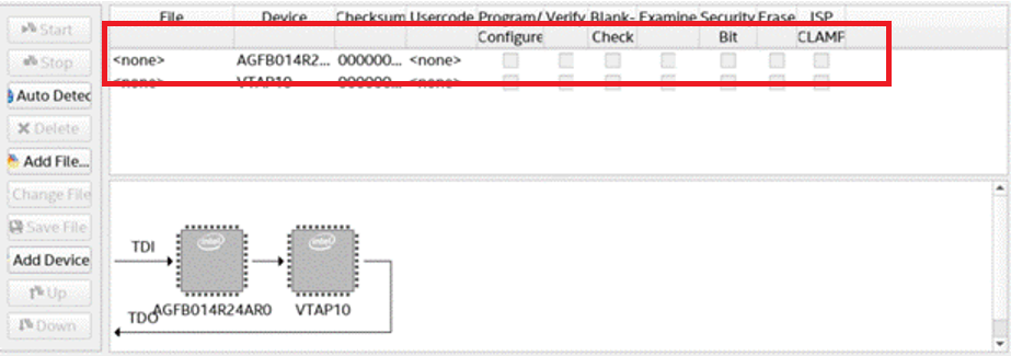
- Right-click the row in the file list, and then click Change File.
Figure 27. Programmer Window

- Browse to select the .sof file.
- Enable the Program/Configure option for the row.
Figure 28. Program/Configure Option
- Click Start. The progress bar reaches 100% when device configuration is complete. The device is now fully configured and in operation.
Figure 29. Programming SuccessfulNote: If device configuration fails, confirm that the device you select for configuration matches the device you specify during .sof file generation.