External Memory Interfaces Agilex™ 7 M-Series FPGA IP User Guide
Visible to Intel only — GUID: imp1693106245842
Ixiasoft
- 4.1.2. s0_axi4_clock_out for Agilex 7 M-Series External Memory Interfaces (EMIF) IP - DDR4 Component
- 4.3.2. s0_axi4_clock_out for Agilex 7 M-Series External Memory Interfaces (EMIF) IP - DDR5 Component
Visible to Intel only — GUID: imp1693106245842
Ixiasoft
7.4.8.1. DDR5 Discrete Component/Memory Down Topology: Single Rank x8 or x16, Dual Rank x8 or x16
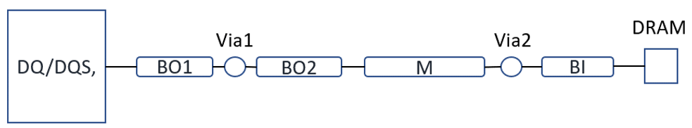
Data Group includes Data Strobe and its complement (DQS and DQS#), Data (DQ), and Data Mask (DM). The connection from the FPGA to DRAM is point-to-point topology as shown in the figure below, for single rank.
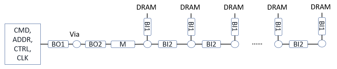
Double rank topology has clamshell/fly-by configuration. For address, command, control and clock signals, a fly-by or clamshell topology is recommended to meet signal-integrity performance and for easier routing. The termination approach for DDR5 is through programmable ondie-termination (ODT). You can adjust the design topology based on the actual PCB design (single rank or dual rank).