Visible to Intel only — GUID: nik1412379643289
Ixiasoft
2.1.1. Constructing Communication Links in the Link Designer Module
2.1.2. Link and Simulation Setting
2.1.3. Transmitter Setting
2.1.4. Receiver Setting
2.1.5. IBIS-AMI Wrapper
2.1.6. Channel Setting
2.1.7. Batch Channel Simulation Configuration
2.1.8. Crosstalk Aggressor Transmitter Setting
2.1.9. Repeater and Retimer Configurations
2.1.10. Noise Source Link Component
2.1.11. System Options
2.1.12. Project Management Functions
2.1.13. Archiving and Unarchiving Projects
2.1.14. Device Model Importer
2.1.15. Analysis Functions and Pre-Simulation and Pre-Analysis Checklists
2.1.16. COM Analysis
Visible to Intel only — GUID: nik1412379643289
Ixiasoft
3.2.3. Completing the System
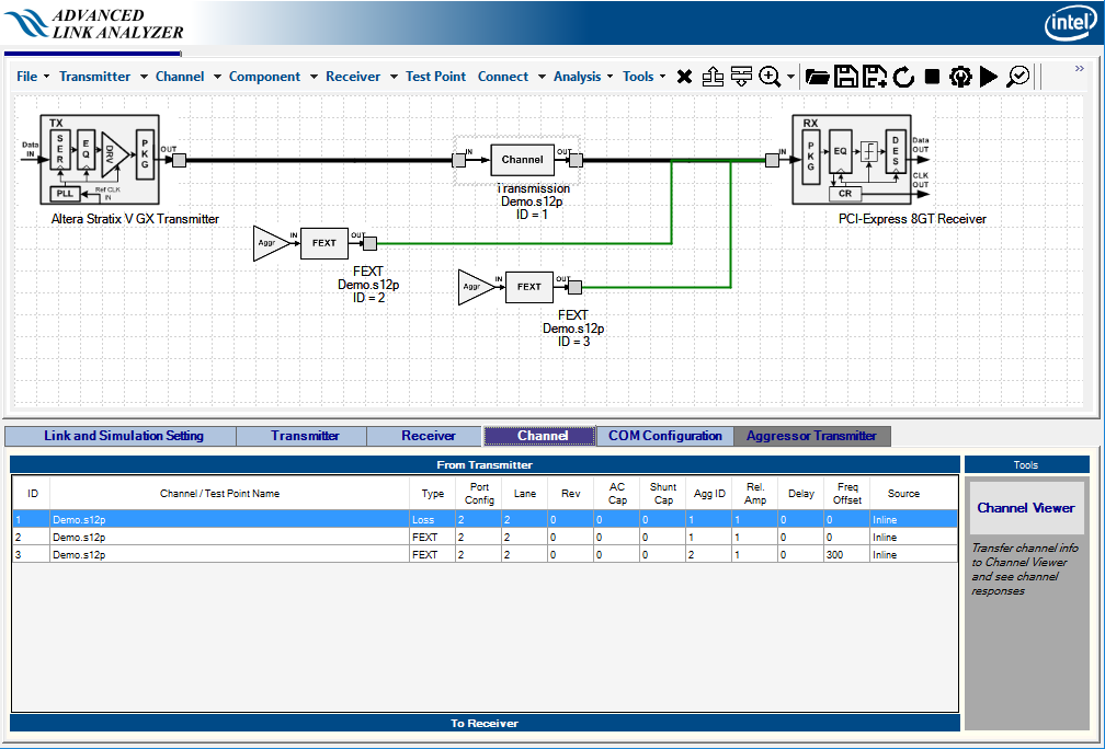
All the link components are now chosen and placed in the Link Designer. Click Connect in the Link Designer to begin connecting the components. Refer to the Link and Simulation Setting section for link construction in the Link Designer. The following figure shows the completed link system.
Figure 206. Complete Link Connection in Link Designer


The link configuration is complete. Use the Save/Save as buttons to save the configuration for later use.
Related Information