Visible to Intel only — GUID: hco1419012531654
Ixiasoft
4.2.1. Example of Scaling
case (exp)

6'b110101 : //-11 Set data equal to MSBs

begin

full_range_real_out[26:0] <= {real_in[15:0],11'b0};

full_range_imag_out[26:0] <= {imag_in[15:0],11'b0};

end
   6'b110110 : //-10 Equals left shift by 10 with sign extension

begin

full_range_real_out[26] <= {real_in[15]};

full_range_real_out[25:0] <= {real_in[15:0],10'b0};

full_range_imag_out[26] <= {imag_in[15]};

full_range_imag_out[25:0] <= {imag_in[15:0],10'b0};

end

6'b110111 : //-9 Equals left shift by 9 with sign extension

begin

full_range_real_out[26:25] <= {real_in[15],real_in[15]};

full_range_real_out[24:0] <= {real_in[15:0],9'b0};

full_range_imag_out[26:25] <= {imag_in[15],imag_in[15]};

full_range_imag_out[24:0] <= {imag_in[15:0],9'b0};

end

   .

   .

   .

endcase
In this example, the output provides a full scale 27-bit word. You must choose how many and which bits must be carried forward in the processing chain. The choice of bits determines the absolute gain relative to the input sample level.
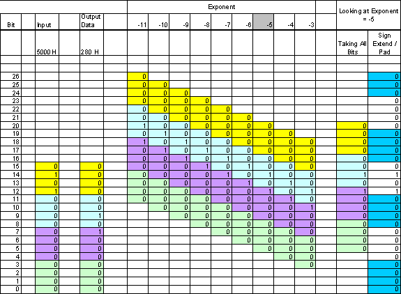
Figure A–1 on page A–5 demonstrates the effect of scaling for all possible values for the 256-point quad output FFT with an input signal level of 0x5000. The output of the FFT is 0x280 when the exponent = –5. The figure illustrates all cases of valid exponent values of scaling to the full scale storage register [26..0]. Because the exponent is –5, you must check the register values for that column. This data is shown in the last two columns in the figure. Note that the last column represents the gain compensated data after the scaling (0x0005000), which agrees with the input data as expected. If you want to keep 16 bits for subsequent processing, you can choose the bottom 16 bits that result in 0x5000. However, if you choose a different bit range, such as the top 16 bits, the result is 0x000A. Therefore, the choice of bits affects the relative gain through the processing chain.
Because this example has 27 bits of full scale resolution and 16 bits of output resolution, choose the bottom 16 bits to maintain unity gain relative to the input signal. Choosing the LSBs is not the only solution or the correct one for all cases. The choice depends on which signal levels are important. One way to empirically select the proper range is by simulating test cases that implement expected system data. The output of the simulations must tell what range of bits to use as the output register. If the full scale data is not used (or just the MSBs), you must saturate the data to avoid wraparound problems.
