Visible to Intel only — GUID: myw1498087326488
Ixiasoft
1.1. Open the Example Design
1.2. Specify EDA Tool Settings
1.3. Generate a Simulator Setup Script Template
1.4. Modify the Simulator Setup Script
1.5. Compile and Simulate the Design
1.6. View Signal Waveforms
1.7. Add Signals to the Simulation
1.8. Rerun Simulation
1.9. Modify the Simulation Testbench
Visible to Intel only — GUID: myw1498087326488
Ixiasoft
1.4. Modify the Simulator Setup Script
Modify the generated simulator setup script to enable specific commands that simulate the IP cores in the project.
- In a text editor, open the /PLL_RAM/mentor/msim_setup.tcl file.
- Create a new text file with the name mentor_example.do and save it in the /PLL_RAM/mentor/ directory.
- In the msim_setup.tcl file, copy the section of code enclosed within the TOP-LEVEL TEMPLATE – BEGIN and TOP-LEVEL TEMPLATE – END comments, and then paste this code into the new mentor_example.do file.
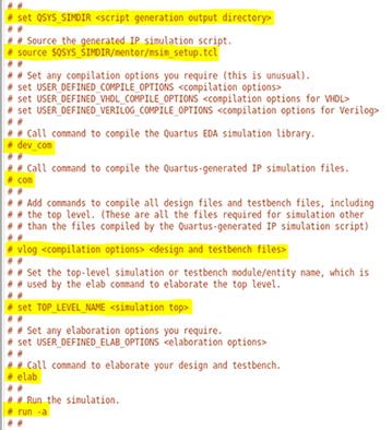
- In the mentor_example.do file, delete the single pound (#) characters preceding the following highlighted lines to enable compilation commands:
Figure 3. Uncomment Highlighted Simulation Commands in the Script

- Replace the following lines in the mentor_example.do script:
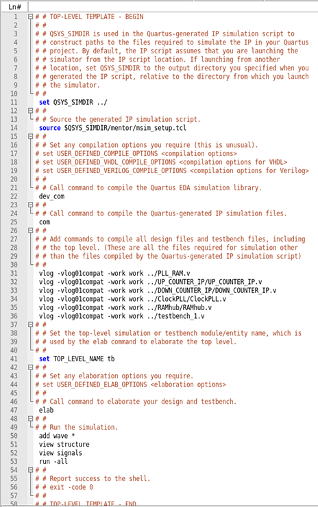
Table 1. Specify Values in the mentor_example.do Script Replace this Line With this Line set QSYS_SIMDIR <script generation output directory> ../ vlog <compilation options> <design and testbench files> vlog -vlog01compat -work work ../PLL_RAM.v vlog -vlog01compat -work work ../UP_COUNTER_IP/UP_COUNTER_IP.v vlog -vlog01compat -work work ../DOWN_COUNTER_IP/DOWN_COUNTER_IP.v vlog -vlog01compat -work work ../ClockPLL/ClockPLL.v vlog -vlog01compat -work work ../RAMhub/RAMhub.v vlog -vlog01compat -work work ../testbench_1.vset TOP_LEVEL_NAME <simulation top> set TOP_LEVEL_NAME tb run -a add wave * view structure view signals run -all - Save the /PLL_RAM/mentor/mentor_example.do file. The following figure shows the mentor_example.do file after revisions are complete:
Figure 4. Completed Top-Level IP Simulation Setup Script
