ModelSim* - Intel® FPGA Edition Simulation Quick-Start: Intel® Quartus® Prime Pro Edition
ID
683305
Date
12/30/2019
Public
Visible to Intel only — GUID: xat1498170642540
Ixiasoft
1.1. Open the Example Design
1.2. Specify EDA Tool Settings
1.3. Generate a Simulator Setup Script Template
1.4. Modify the Simulator Setup Script
1.5. Compile and Simulate the Design
1.6. View Signal Waveforms
1.7. Add Signals to the Simulation
1.8. Rerun Simulation
1.9. Modify the Simulation Testbench
Visible to Intel only — GUID: xat1498170642540
Ixiasoft
1.7. Add Signals to the Simulation
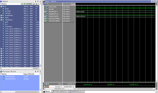
The CLOCK, WE, OFFSET, RESET_N, and RD_DATA signals automatically appear in the Wave window because the top-level design defines these I/O. In addition, you can optionally add internal signals to the simulation.
- In the Objects window, locate the UP_module, DOWN_module, PLL_module, and RAM_module modules.
- In the Objects window, select RAM_module. The module's inputs and outputs display.
Figure 9. Add Signals To Wave Window

- To add the internal signals between the down-counter and dual-port RAM module, right-click rdaddress and then click Add Wave.
- To add the internal signals between the up-counter and dual-port RAM module, right-click wraddress and then click Add Wave. Alternatively, you can drag and drop these signals from the Objects window to the Wave window.
- To generate the waveforms for the new signals you add, click Simulate > Run > Continue.