2.3. Simulating the Design Example
The simulation setup involves the use of a Root Port Bus Functional Model (BFM) to exercise the P-tile Avalon® Streaming IP for PCIe (DUT) as shown in the following figure.
Figure 15. PIO Design Example Simulation Testbench
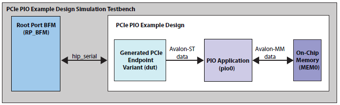
For more details on the testbench and the modules in it, refer to Testbench.
The following flow diagram shows the steps to simulate the design example:
Figure 16. Procedure
- Change to the testbench simulation directory, <project_directory>/pcie_ed_tb/pcie_ed_tb/sim/<EDA_vendor>/simulator.
- Run the simulation script for the simulator of your choice. Refer to the table below.
- Analyze the results.
Note: P-Tile does not support parallel PIPE simulations.
| Simulator | Working Directory | Instructions |
|---|---|---|
| ModelSim* SE, Siemens* EDA QuestaSim*- Intel® FPGA Edition | <example_design>/pcie_ed_tb/pcie_ed_tb/sim/mentor/ |
|
| VCS* | <example_design>/pcie_ed_tb/pcie_ed_tb/sim/synopsys/vcs |
Note:
To run a simulation in interactive mode, use the following steps: (if you already generated a simv executable in non-interactive mode, delete the simv and simv.diadir)
|
This testbench simulates up to a Gen4 x16 variant.
The simulation reports, "Simulation stopped due to successful completion" if no errors occur.