Processor Integration Overview for LGA115x-based Intel® Processors
Content Type: Install & Setup | Article ID: 000005918 | Last Reviewed: 10/06/2020
The following overview and installation instructions are for professional system integrators building ATX form factor PCs that use Intel® Boxed Processors in the LGA115x-land package with industry-accepted motherboards, chassis, and peripherals. It contains technical information intended to aid in system integration.
Visit the Intel® Processor Installation Center for more material on LGA115x-based installation.
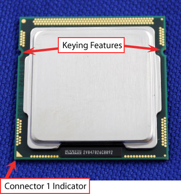
| Note | This integration documentation refers to the installation of both LGA1156-based processors and fan heat sinks and LGA1155-based processors and fan heat sinks due to the similarity between the two installations. The same fan heat sinks may be used across the two sockets if the Thermal Design Profile (TDP) of the processor is the same. The fan heat sink installation is identical across both sockets. Be aware that LGA1156- and LGA1155-based processors are not compatible between sockets due to electrical, mechanical, and keying differences. You risk damaging either the processor or the socket if you try and install a LGA1156-based processor in a LGA1155 socket or vice versa. |
Click or the topic for details:
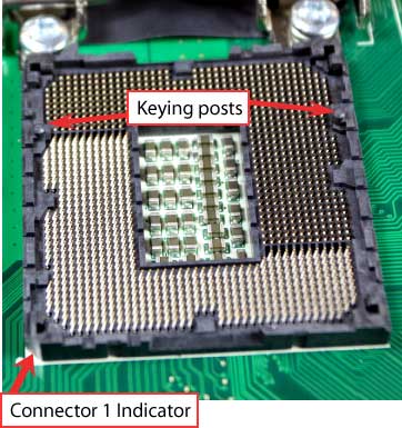
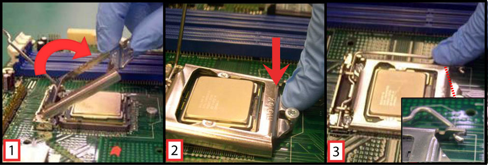
Opening the socket
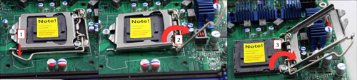
| Note | Apply pressure to the corner with your right-hand thumb when opening or closing load lever. Otherwise, the lever bounces back causing bent contacts. |
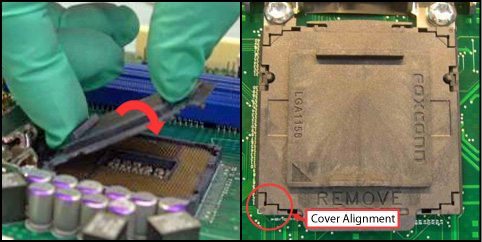
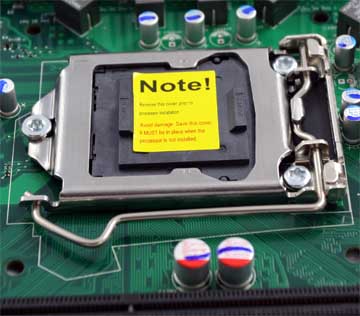
Removing the socket protective cover
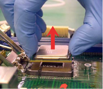
| Note | We do not recommend vertical removal, as it requires higher force and can lead to socket contact damage. |
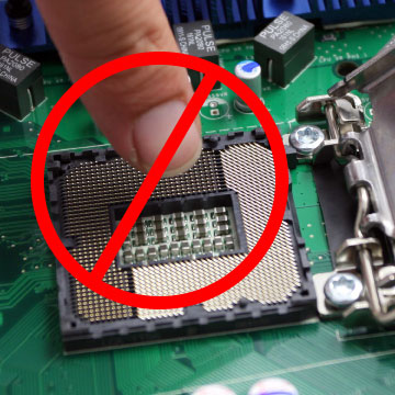
Caution | Never touch fragile socket contacts to avoid damage. |
Inspecting for bent contacts
Inspect socket contacts from different angles to make sure none are damaged. If any are damaged, do not use the motherboard.| Note | If any socket or motherboard is suspected of being mishandled, the socket should be examined. |
Five types of contact damage to look for (see Table 1 below for potential causes and solutions):
Figure 1: Contact is bent backwards upon itself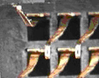 | Figure 2: Contact is bent forward or downward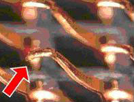 |
Figure 3: Contact is bent sideways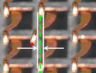 | Figure 4: Contact tip is bent up or missing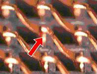 |
Table 1: Bent contact causes and corrective actions
| Failure Type | Potential Causes | Possible Corrective Action |
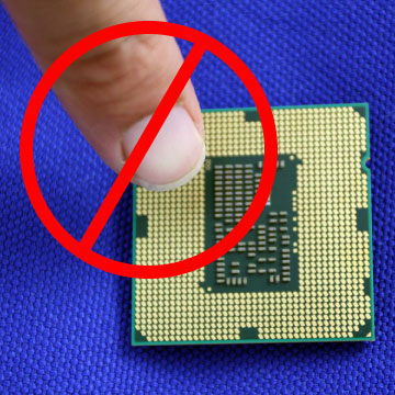
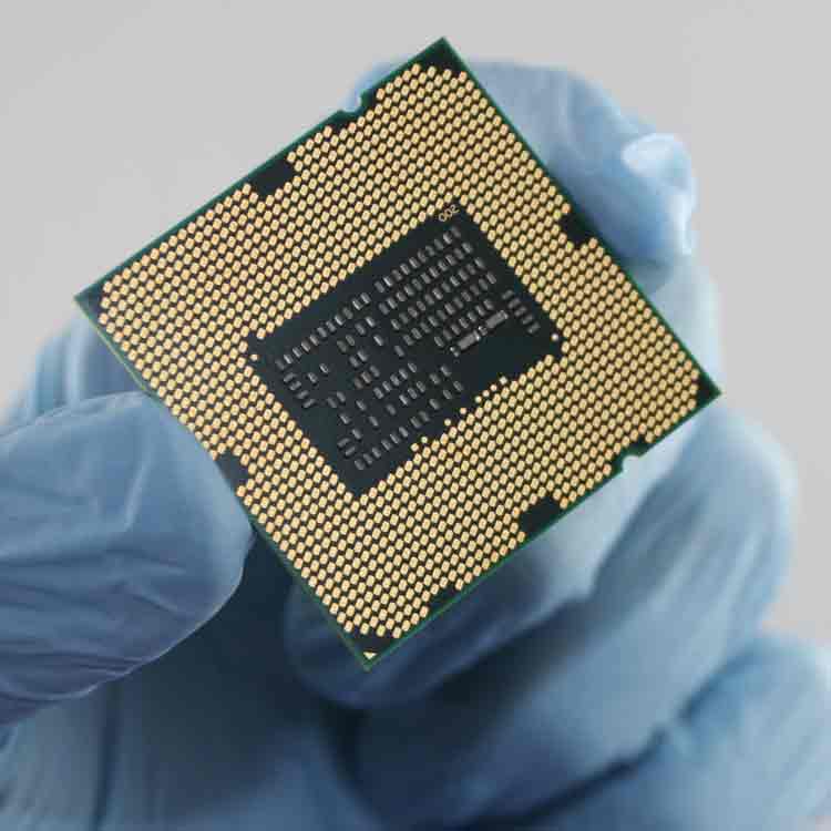
| 1,5 | CPU tilted during installation or removal Glove/finger snag | Verify CPUs are installed and removed vertically ONLY Vacuum wands may be considered Verify CPUs are being held by the substrate edge ONLY |
| 1,5 | Glove/finger snag CPU capacitors dragging | Verify packages are held by substrate edges ONLY Verify CPUs are lifted and placed vertically ONLY Vacuum wands may be considered |
| 2 | CPU tilted during installation or removal CPU dragged across contacts during installation or removal CPU dropped during installation or removal Socket protective cover dropped into socket | Verify packages are held by substrate edges ONLY Verify CPUs are lifted and placed vertically ONLY Vacuum wands may be considered |
| 3 | CPU tilted during installation or removal CPU dragged across contact array Glove/finger snag | Verify packages are held by substrate edges ONLY Verify CPUs are lifted and places vertically ONLY Vacuum wands may be considered |
| 4 | Socket supplier defect Glove/finger snag CPU capacitors dragging Return motherboard to manufacture | Verify packages are held by substrate edges ONLY Verify CPUs are lifted and places vertically ONLY Vacuum wands may be considered |
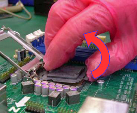
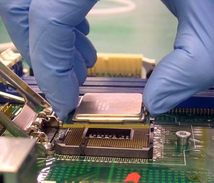
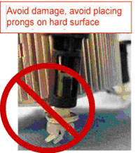
| Note | Tilting or roughly shifting it into place can damage socket contacts. |
| Caution | Do not use a vacuum pen for installation. |
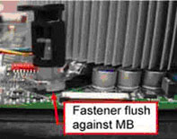
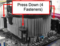
| Note | The thermal solution integration procedures should be performed with the motherboard in the chassis to provide proper clearance under the motherboard for the fastener mechanisms. |
| Note | Thermal solutions that come with the Boxed Intel® processor use pre-applied thermal interface material (TIM) and do not need grease. |
| Caution | Do not to touch or disturb the TIM on the heat sink during installation. If the TIM is disturbed contact customer support. |
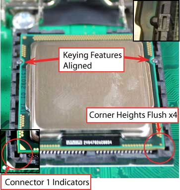
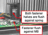
Inspection 1
Actuate fasteners (see image below):
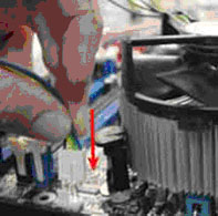
Inspection 2 (see image below):
| Note | Be sure to take the proper electrostatic discharge (ESD) precautions (ground straps, gloves, ESD mats, or other protective measures) to avoid damaging the processor and other electrical components in the system. |
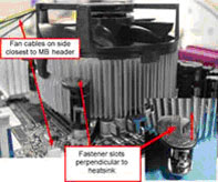
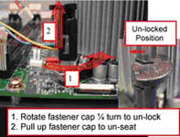
Follow these steps to remove the boxed processor fan heat sink from the system (see image below):
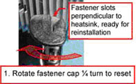
| Note | To re-assemble the heat sink, reset the fastener caps to their original position with the slot perpendicular to the heat sink. Re-attach cable to cable management clips. Then, follow the assembly instructions (see image below). |
| Note | Every time the heat sink is removed from the processor, it is critical that the thermal interface material be replaced, in order to ensure proper thermal transfer to the boxed processor fan heat sink. |