2. Running the Remote Debugging Over a PCIe Interface Example Design
Validated Environment
| FPGA Development Kit | DK-DEV-1SGX-L-A (Comes with a 1SG280LU2F50E2VG device) For details, visit the Intel® Stratix® 10 GX FPGA Development Kit web page. |
| Operating System | Ubuntu 16.04 LTS |
| Required Operating System Driver | uio_pci_generic - Provided by the operating system |
| Required Application | etherlink - Source code is available on GitHub at https://github.com/altera-opensource/remote-debug-for-intel-fpga Instructions for downloading and compiling the etherlink application are included in the steps that follow. |
| Intel® Quartus® Prime Pro Edition Programmer version | 21.3 |
| gcc --version | 5.4.0 |
| cmake --version | 3.22.2 |
The remaining instructions assume that the Intel® Stratix® 10 GX FPGA Development Kit is already installed into the host system.
Procedure
- Download the JTAG remote debugging over a PCIe interface example design from the Intel® FPGA Design Store at the following URL:
https://www.intel.com/content/www/us/en/design-example/733510/
- Unzip the example design package to temporary location.
- Use the Intel® Quartus® Prime Programmer to program the Intel® Stratix® 10 GX FPGA Development Kit with the pcie_remote_debug.sof programming file:
For example, for a cable called 1 and the programming file in the current folder of your terminal session, you can run the following command:For help with the Intel® Quartus® Prime programmer command, run the following command:
- Restart or reboot the host machine so that the design can go through the PCIe enumeration process with the newly programmed design:
- After reboot completes and you are logged back on, search for the FPGA card with the one of the following commands:
- lspci -nn
- lspci -nn | grep Altera
You are looking for a connection that looks similar to the following one: - Ensure that your FPGA card is bound to the uio_pci_generic PCIe driver as follows:
- Confirm that you do not have a PCIe driver associated with the FPGA card with the command that follows. In the command, PCI bus address is 0000:01:00.0. Your card might have different device information.
If this command returns the following response, continue to step 6.
- If the command returned a driver other than uio_pci_generic, unbind that driver from the FPGA board with the following command:
- Load the uio_pci_generic driver and then use the new_id to bind the UIO driver to the FPGA board. The vendor ID and device ID information is specific to your Intel® Stratix® 10 GX FPGA Development Kit PCIe card.
- Verify that the uio_pci_generic driver is bound to the FPGA card: If this command returns the following response, continue to step 6.
- If you get a does not exist response, run the following bind command:
Use the ls -l /sys/bus/pci/devices/0000:01:00.0/driver command to confirm that the uio_pci_generic driver is bound to the FPGA card.
- Confirm that you do not have a PCIe driver associated with the FPGA card with the command that follows. In the command, PCI bus address is 0000:01:00.0. Your card might have different device information.
- Ensure that required read and write permissions are in place for PCIe BAR4 with the following command:
- Download and compile the etherlink application:
The etherlink application listens to the JTAG server and communicates with the PCIe device to read and write to the JTAG-Over-Protocol IP that handles all the JTAG communication for debug applications within the FPGA device.
- Ensure that the etherlink application is executable and run the application with the following command:
The --start-address option references the starting address for the JTAG-Over-Protocol (JOP) IP in the Avalon® memory-mapped interface system mapping. The --address-span option references the depth of the memory buffers used in the JOP IP. You can edit these values for the JOP IP in the Intel® Quartus® Prime IP Parameter Editor.
If the etherlink command runs successfully, you get output similar to the following messages:INFO: Etherlink Server Configuration: INFO: H2T/T2H Memory Size : 4096 INFO: Listening Port : 0 INFO: IP Address : 0.0.0.0 INFO: UIO Platform Configuration: INFO: Driver Path: /sys/bus/pci/devices/0000:01:00.0/resource4 INFO: Address Span: 16384 INFO: Start Address: 0x0 INFO: Server socket is listening on port: 36181
The port is the TCP/IP port that the etherlink application listens to. After the etherlink application establishes the port, you can specify the port in the --port=<port_number> option of the etherlink command.
Take note of the listening port, IP address, and server socket port from the output message. You need that information in the next step.
- In a new terminal session, start the JTAG server specifying the IP address and listening port of the etherlink application, as well as telling the JTAG server to expect communication with the JOP IP:
Obtain values for <etherlink IP address>, <server socket listening port>, and <etherlink server listening port> from the output message of the previous step.
For example, based on the output from the previous step, the command to start the JTAG server is as follows: - Confirm that you are connected to the FPGA device by running the following command in the same terminal window as the previous step: If you are connected to the FPGA device, you get output similar to the following messages:
1) JTAG-over-protocol [sti://localhost:0/intel/remote-debug/0.0.0.0:36587/0]
  020D10DD   VTAP10
  Design hash    EDB83A4DEAAA1A68428D
  + Node 30006E00  Signal Tap #0
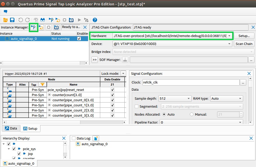
- On the host machine, start Signal Tap GUI and open the stp_test.stp file provided with the example design. On the JTAG Chain Configuration tab, ensure that you select JTAG-over-protocol in the Hardware field.
After you run a signal acquisition, your GUI resembles the following example:Figure 2. Signal Tap GUI After Acquiring Signals Through JTAG-Over-Protocol
If you zoom in, you should see the counter pipeline similar to the following image:Figure 3. Signal Tap GUI Showing Counter Pipeline
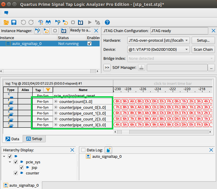
If can see the counter pipeline, you have successfully captured FPGA data on Signal Tap over your PCIe connection!