Visible to Intel only — GUID: xop1633471022804
Ixiasoft
Visible to Intel only — GUID: xop1633471022804
Ixiasoft
10.1.4.2. Toolkit Parameters
The Toolkit parameters window has the following sub-tabs.
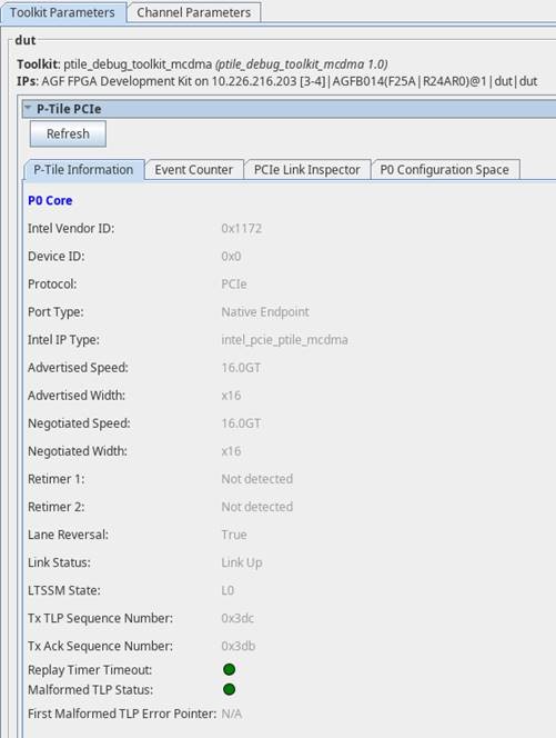
P-Tile Information
This lists a summary of the P-Tile PCIe IP parameter settings in the PCIe IP Parameter Editor when the IP was generated, as read by the P-Tile Debug Toolkit when initialized. If you have port bifurcation enabled in your design (for example, x8x8), then this tab will populate the P-Tile information for each core (P0 core, P1 core, etc.).
All the information is read-only.
Use the Refresh button to read the settings.
| Parameter | Values | Descriptions |
|---|---|---|
| Intel Vendor ID | 1172 | Indicates the Vendor ID as set in the IP Parameter Editor. |
| Device ID | 0 | This is a unique identifier for the device that is assigned by the vendor. |
| Protocol | PCIe | Indicates the Protocol. |
| Port Type | Root Port, Endpoint 1 | Indicates the Hard IP Port type. |
| Intel IP Type | intel_pcie_mcdma | Indicates the IP type used. |
| Advertised speed | Gen3, Gen4 | Indicates the advertised speed as configured in the IP Parameter Editor. |
| Advertised width | x16, x8 | Indicates the advertised width as configured in the IP Parameter Editor. |
| Negotiated speed | Gen3, Gen4 | Indicates the negotiated speed during link training. |
| Negotiated width | x16, x8 | Indicates the negotiated link width during link training. |
| Link status | Link up, link down | Indicates if the link (DL) is up or not. |
| LTSSM State | Refer to the F-Tile Avalon Streaming Intel FPGA IP for PCI Express User Guide | Indicates the current state of the link. |
| Lane Reversal | True, False | Indicates if lane reversal happens on the link. |
| Retimer 1 | Detected, not detected | Indicates if a retimer was detected between the Root Port and the Endpoint. |
| Retimer 2 | Detected, not detected | Indicates if a retimer was detected between the Root Port and the Endpoint. |
| Tx TLP Sequence Number | Hexadecimal value | Indicates the next transmit sequence number for the transmit TLP. |
| Tx Ack Sequence Timeout | Hexadecimal value | Indicates the ACK sequence number which is updated by receiving ACK/NAK DLLP. |
| Replay Timer Timeout | Green, Red | Green: no timeout Red: timeout |
| Malformed TLP Status | Green, Red | Green: no malformed TLP Red: malformed TLP detected |
| First Malformed TLP Error Pointer |
|

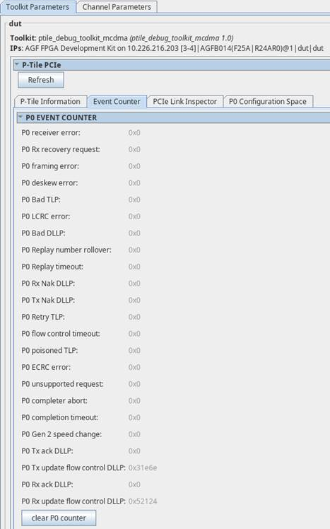
Event Counter
This tab allows you to read the error events like the number of receiver errors, framing errors, etc. for each port. You can use the Clear P0 counter/Clear P1 counter to reset the error counter.

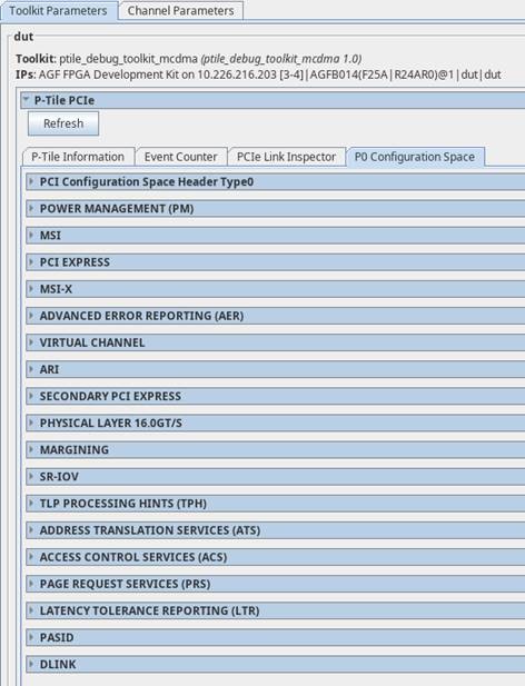
P0/P1 Configuration Space
This tab allows you to read the configuration space registers for that port. You will see a separate tab with the configuration space for each port.
