AN 855: PCI Express* High Performance Reference Design for Intel® Cyclone® 10 GX
ID
683504
Date
6/08/2018
Public
Visible to Intel only — GUID: oxn1526591539615
Ixiasoft
1.1. Understanding Throughput in PCI Express
1.2. Deliverables Included with the Reference Design
1.3. Reference Design Functional Description
1.4. Hardware Requirements
1.5. Software Requirements
1.6. Software Installation
1.7. Hardware Installation
1.8. Running the Software Application
1.9. Additional Chaining DMA Commands
1.10. Using SignalTap II
1.11. Performance Benchmarking Results
1.12. Document Revision History
Visible to Intel only — GUID: oxn1526591539615
Ixiasoft
1.8. Running the Software Application
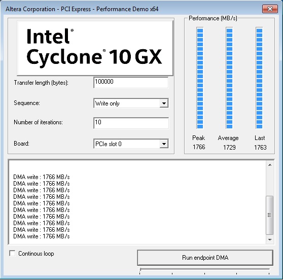
The software GUI has the following control fields:
- Transfer length—Specifies the transfer length in bytes
- Sequence—Controls the sequence for data transfer or addressing
- Number of iterations—Controls the number of iterations for the data transfer
- Board—Specifies the development board for the software application
- Continuous loop—When this option is turned on, the application performs the transfer continuously
- Set the Transfer length to 100,000 bytes and the Sequence to Write only, Click Run.
When set for Write only, the software programs the DMA registers in the FPGA to transfer data from the FPGA to the system memory in chunks of 100,000 bytes. The performance bars report the peak, average, and last throughput. The average throughput is computed across all the iterations.
- You can use the GUI to change the Transfer length and Sequence and repeat the test.
Figure 6. Write-Only Options

- Double-click on the application Windows_for_AVST_On_Chip_Mem in the Windows_for_AVST_On_Chip_Mem directory.
- The application reports the board type, the number of active lanes, the maximum read request size, and the maximum payload size.