Visible to Intel only — GUID: nik1412379581414
Ixiasoft
Visible to Intel only — GUID: nik1412379581414
Ixiasoft
2.1.3.1. Jitter/Noise Component
The following figure shows the jitter decomposition diagram and the breakdown of jitter components:

| Name |
Description |
Unit |
Support in Intel® Advanced Link Analyzer |
Comments |
|---|---|---|---|---|
| DJ |
Deterministic Jitter |
Unit Interval (UI) |
Yes |
DJ can be generated using a uniform distribution, dual-Dirac, or truncated Gaussian method. Select the DJ generation method in the Transmitter Jitter/Noise Options Window. The default DJ method is dual-Dirac. DJ consists of periodic jitter, bounded uncorrelated jitter, inter-symbol interference, and duty-cycle distortion. The DJ value is used in the simulation when the DJ/RJ-DN/RN method is selected. |
| ISI |
Inter-Symbol Interference |
UI |
Yes |
ISI can be generated using a uniform distribution, dual-Dirac, or truncated Gaussian method. Select the ISI generation method in the Transmitter Jitter/Noise Options Window. The default ISI method is dual-Dirac. |
| DCD |
Duty Cycle Distortion |
UI |
Yes |
The DCD parameter models two types of jitter: Positive pulse width jitter (PPWJ) and Clock DCD. The PPWJ shortens or lengthens the logic 1 waveform. The Clock DCD emulates distorted clock waveform effects on the transmitter output waveform. You can select the DCD generation method in the Transmitter Jitter/Noise Options Window. The default DCD method is PPWJ – (shortened positive waveform). |
| BUJ |
Bounded Uncorrelated Jitter |
UI |
Yes |
Same as Deterministic Jitter. The default BUJ method is Uniform distribution. |
| RJ |
Random Jitter |
UI-RMS or ps-RMS |
Yes |
RJ is assumed to be Gaussian. RJ can be specified in either pico-second (ps-RMS) or UI-RMS. |
| SJ |
Sinusoidal Jitter |
Amplitude: UI Frequency: MHz |
Yes |
Sinusoidal jitter can be specified with amplitude and frequency. |
| DN |
Deterministic Noise |
mV |
Yes |
DN can be generated using a uniform distribution, dual-Dirac, or truncated Gaussian method. You can select the DN generation method in the Transmitter Jitter/Noise Options Window. The default DN method is uniform. |
| BUN |
Bound Uncorrelated Noise |
mV |
Yes |
Same as DN. The default method is the Truncated Gaussian method with a Peak-to-RMS ratio of 14. You can select the BUN generation method and parameters in the Transmitter Jitter/Noise Options Window. |
| RN |
Random Noise |
mV-RMS |
Yes |
RN is assumed to be Gaussian. |
| Jitter PDF |
Jitter Probability Density Function (PDF) |
Jitter amplitude, Probability (Jitter amplitude can be in absolute time or UI (unit interval) unit) |
Yes |
Jitter PDF defines the jitter probability density function. The input format is jitter amplitude in second and probability. The following is a jitter PDF example: -5e-12 1e-10 -4e-12 3e-7 -3e-12 1e-4 -2e-12 1e-2 -1e-12 0.29 0 0.4 1e-12 0.29 2e-12 1e-2 3e-12 1e-4 4e-12 3e-7 5e-12 1e-10 |
| Noise PDF |
Noise Probability Density Function |
Noise amplitude, Probability |
Yes |
Noise PDF defines the noise probability density function. The input format is Noise amplitude in volt and probability. The following is a noise PDF example: -50e-3 1e-10 -40e-3 3e-7 -30e-3 1e-4 -20e-3 1e-2 -10e-3 0.29 0 0.4 10e-3 0.29 20e-3 1e-2 30e-3 1e-4 40e-3 3e-7 50e-3 1e-10 |
| CMN |
Common Mode Noise |
mV-rms |
Yes |
It injects common noise into the link. You can specify the location of the noise injection either after the package or after the die. |
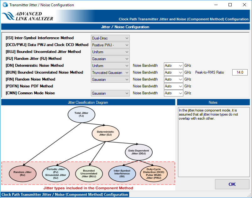
Click Jitter/Noise Options to further configure each jitter and noise type. There are two jitter/noise modes for Intel® Advanced Link Analyzer’s transmitters: Jitter/Noise Component mode and DJ/RJ-DN/RJ mode. Only one jitter/noise mode is active at a time, and you must determine which mode to use in your simulations. Refer to Characterization Data Access for usage and meaning of Linked to Characterization Data check box in the Jitter/Noise panel.
- Jitter/Noise Component mode— Intel® Advanced Link Analyzer uses a flat jitter/noise structure that assumes no overlapping among all the jitter and noise components. Avoid double counting when inputting or importing jitter/noise figures. The following figure shows six specific jitter components: DCD, ISI, SJ, BUJ, RJ, and jitter PDF. The noise components DN, BUN, RN, and noise PDF must also be specified separately.
Figure 20. Specifying Transmitter Jitter and Noise in Jitter/Noise Mode
 Figure 21. Transmitter Jitter/Noise Configuration in Jitter/Noise Component Mode
- DJ/RJ-DN/RJ mode—All deterministic jitter/noise components are included in DJ and DN.
Figure 22. Specifying Transmitter Jitter and Noise in DJ/RJ-DN/RJ Mode
 Figure 23. Transmitter Jitter/Noise Configuration in DJ/RJ-DN/RJ Method
- Clock Jitter/Noise—Clock path transmitter uses the same jitter/noise configuration method as the data path transmitter’s jitter/noise component mode.
Figure 24. Specifying Clock Path Transmitter Jitter/Noise

