A newer version of this document is available. Customers should click here to go to the newest version.
2.1.1. Constructing Communication Links in the Link Designer Module
2.1.2. Link and Simulation Setting
2.1.3. Transmitter Setting
2.1.4. Receiver Setting
2.1.5. IBIS-AMI Wrapper
2.1.6. Channel Setting
2.1.7. Batch Channel Simulation Configuration
2.1.8. Crosstalk Aggressor Transmitter Setting
2.1.9. Repeater and Retimer Configurations
2.1.10. Noise Source Link Component
2.1.11. System Options
2.1.12. Project Management Functions
2.1.13. Archiving and Unarchiving Projects
2.1.14. Device Model Importer
2.1.15. Analysis Functions and Pre-Simulation and Pre-Analysis Checklists
2.1.16. COM Analysis
2.1.3.3. Characterization Data Access
Characterization Data Access—Transmitter jitter values can be retrieved from the built-in device characterization database.
Note: Advanced Link Analyzer supports Intel® Arria® 10 GX/SX/GT, Stratix® V GT, Stratix® V GX and Arria® V GZ, and Intel® Stratix® 10 L-tile/H-tile/E-tile characterization database access upon request. For devices supported by IBIS-AMI Wrapper Technology, jitter/noise models are provided by the IBIS-AMI models, and the wrapper determines the correct jitter/noise values associated with the link settings. If you need this capability, contact My Intel support.
Use the following guidelines for characterization data access:
- When Stratix® V GX, Stratix® V GT, Arria® V GZ, Intel® Arria® 10 GX/SX/GT, Intel® Stratix® 10 L-Tile/H-Tile/E-Tile/P-Tile, or Intel® Agilex™ E-Tile/P-Tile is selected, the Characterization Data Access button appears and you can include the transmitter jitter parameters in the simulation.
- Characterization Data Access covers PVT variations. You can select appropriate process, voltage, and temperature conditions that best match the desired operation conditions.
- After clicking the button, Characterization Data Access configures Advanced Link Analyzer to use the characterization data by:
- Selecting Jitter/Noise Component Mode for characterization data entries
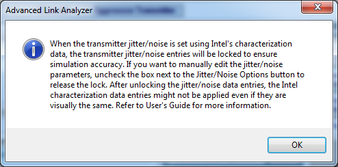
- Turning on Jitter/Noise Data Lock
- Importing device characterization data based on the jitter unit selection
- RJ—Unit selection can be UI (RMS) or ps (RMS)
- Other Jitter—Unit selection can be UI (pk-pk), UI (pk), ps (pk-pk), or ps (pk)
These actions inform the Advanced Link Analyzer simulation engine to use the characterization data from the database.
Note:
- The characterization data is displayed in the text box for reference purposes. The Advanced Link Analyzer simulation engine uses proprietary algorithms to accurately model the jitter and noise in the simulations.
- You can unlock the jitter and noise contents by turning off Jitter/Noise Data Lock. However, the jitter and noise models and values can be different from those when Jitter/Noise Data Lock is turned on.
- Characterization Data Access is supported when the data rate is in the following range:
- Stratix® V GX: 5 Gbps to 14.1 Gbps
- Stratix® V GT: 19.6 Gbps to 28.1 Gbps
- Intel® Stratix® 10 L-tile: 3 Gbps to maximum data rate specified in the data sheet (Typical PVT only)
- Arria® V GZ: 5 Gbps to 14.1 Gbps
- Intel® Arria® 10 GX/SX: 3 Gbps to 17.4 Gbps
- Intel® Arria® 10 GT: 3 Gbps to maximum data rate specified in the data sheet
- Intel® Stratix® 10 L-tile: As per Intel® Stratix® 10 L-tile specifications
- Intel® Stratix® 10 H-tile: As per Intel® Stratix® 10 H-tile specifications
- Intel® Stratix® 10 E-tile: As per Intel® Stratix® 10 E-tile specifications
- Intel® Stratix® 10 P-tile: As per Intel® Stratix® 10 P-tile specifications
- Intel® Agilex™ E-tile: As per Intel® Agilex™ E-tile specifications
- Intel® Agilex™ P-tile: As per Intel® Agilex™ P-tile specifications
- Intel® Agilex™ R-tile: As per Intel® Agilex™ R-tile specifications
- Intel® Agilex™ F-tile: As per Intel® Agilex™ F-tile specifications
- After changing the link and device configurations, such as data rate, VOD, PLL type and bandwidth, and PVT condition, you must update the jitter value by clicking Characterization Data Access.
- When Jitter/Noise Data Lock is turned on, Advanced Link Analyzer examines whether the jitter data matches the simulation configuration during the following conditions:
- Start simulation
- Save link configuration
- In batch simulation mode, jitter data is retrieved and calculated based on the link configuration
When the link configuration exceeds the supporting range of Characterization Data Access, a warning message (conditions 1 and 2) is shown and jitter is reset (all conditions).
Figure 31. Characterization Data Access: PVT Conditions and Jitter/Noise Lock


Figure 32. Characterization Data Access Usage and Message

