Visible to Intel only — GUID: qga1626808030527
Ixiasoft
1. Overview of the Intel® FPGA Power and Thermal Calculator
2. Setting Up the Intel® FPGA Power and Thermal Calculator
3. Intel® FPGA Power and Thermal Calculator Graphical User Interface
4. Intel® FPGA Power and Thermal Calculator Pages
5. Factors Affecting the Accuracy of the Intel® FPGA Power and Thermal Calculator
6. Intel® FPGA Power and Thermal Calculator User Guide Archive
7. Document Revision History for the Intel® FPGA Power and Thermal Calculator User Guide
A. Measuring Static Power
4.1. Intel® FPGA PTC - Power Summary
4.2. Intel® FPGA PTC - Common Page Elements
4.3. Intel® FPGA PTC - Device Selection and Thermal Analysis Windows
4.4. Intel® FPGA PTC - Main Page
4.5. Intel® FPGA PTC - Logic Page
4.6. Intel® FPGA PTC - RAM Page
4.7. Intel® FPGA PTC - DSP Page
4.8. Intel® FPGA PTC - Clock Page
4.9. Intel® FPGA PTC - PLL Page
4.10. Intel® FPGA PTC - I/O Page
4.11. Intel® FPGA PTC - I/O-IP Page
4.12. Intel® FPGA PTC - Transceiver Page
4.13. Intel® FPGA PTC - HPS Page
4.14. Intel® FPGA PTC - Crypto Page ( Intel® Agilex™ Devices with Crypto Blocks Only)
4.15. Intel® FPGA PTC - HBM Page ( Intel® Stratix® 10 Devices Only)
4.16. Intel® FPGA PTC - Thermal Page
4.17. Intel® FPGA PTC - Report Page
Visible to Intel only — GUID: qga1626808030527
Ixiasoft
2.4. Power Analysis for Dual-Core 1SG10M Intel® Stratix® 10 Devices
Some devices, such as the Intel® Stratix® 10 1SG10M, contain two core dies, and are not directly supported by the Intel® FPGA Power and Thermal Calculator (PTC). Power estimations for these devices require use of a separate calculator, together with certain outputs from the PTC and some transceiver details.
Package Details
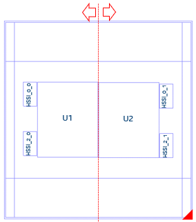
The device package contains two core fabric dies, each with two associated transceivers. In the figure below, U1 and U2 identify the two core fabric tiles, with HSSI_* identifying their respective transceivers.
Figure 1. Dual-core Package Layout
Generating a PTC File and Importing the Data Into the PTC
- In the Intel® Quartus® Prime software, generate a PTC file for your design, for the U1 tile.
- Create a script file for U1 (for example, design_u1.epe_script) containing the following lines:
import,<U1_name>.ptc export_output_fields, <U1_name>.epe_dump - Generate an epe_dump file for U1, by running the following command:
quartus_ptc --epe_test_command=runscript --epe_input=design_u1.epe_script --family=nadder - Download the 1SG10M_Calculator spreadsheet from the Power Estimators and Power Analyzer page.
- Open the 1SG10M_Calculator spreadsheet.
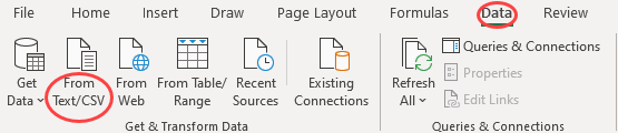
- Import the .epe_dump file into the spreadsheet, by clicking on Data in the spreadsheet menu bar, and then selecting the From Text/CSV icon.
Figure 2. Spreadsheet Menu Bar
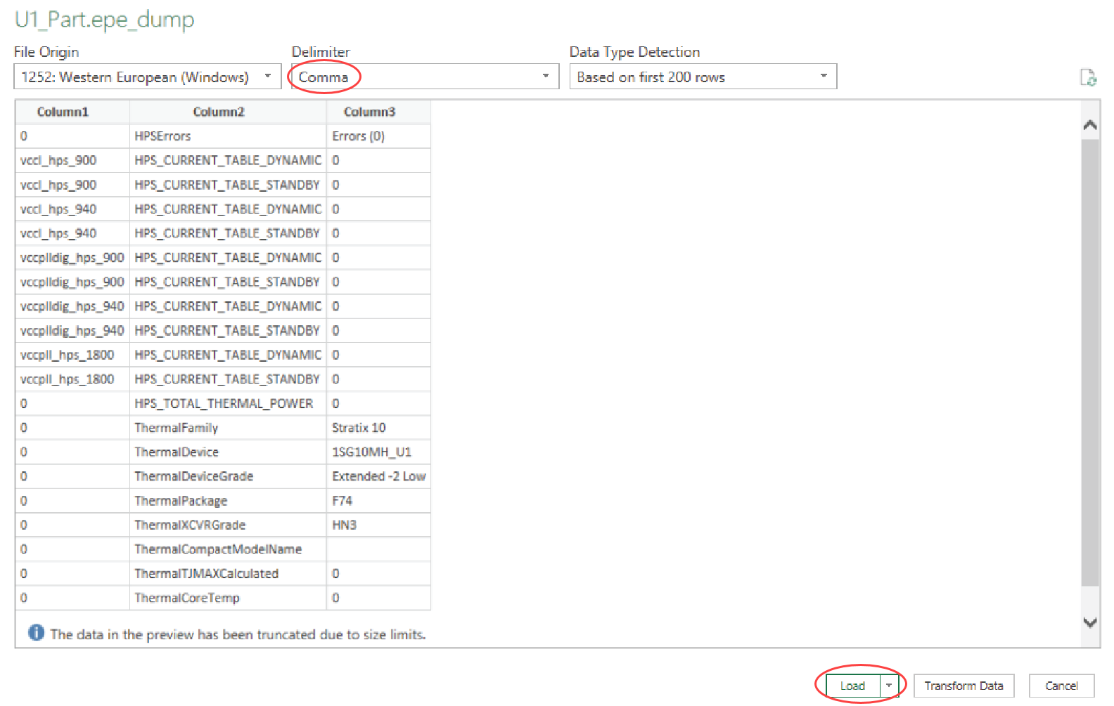
- Select the <U1_name>.epe_dump file that you generated in step 3, above.
- Ensure that Comma is selected in the Delimiter field, and click Load.
Figure 3. Specifying Comma Delimiters
- After the .epe_dump file has loaded, copy all the data from the newly generated worksheet and paste it into the U1 worksheet, replacing any existing data there.
Figure 4. Newly Generated Worksheet
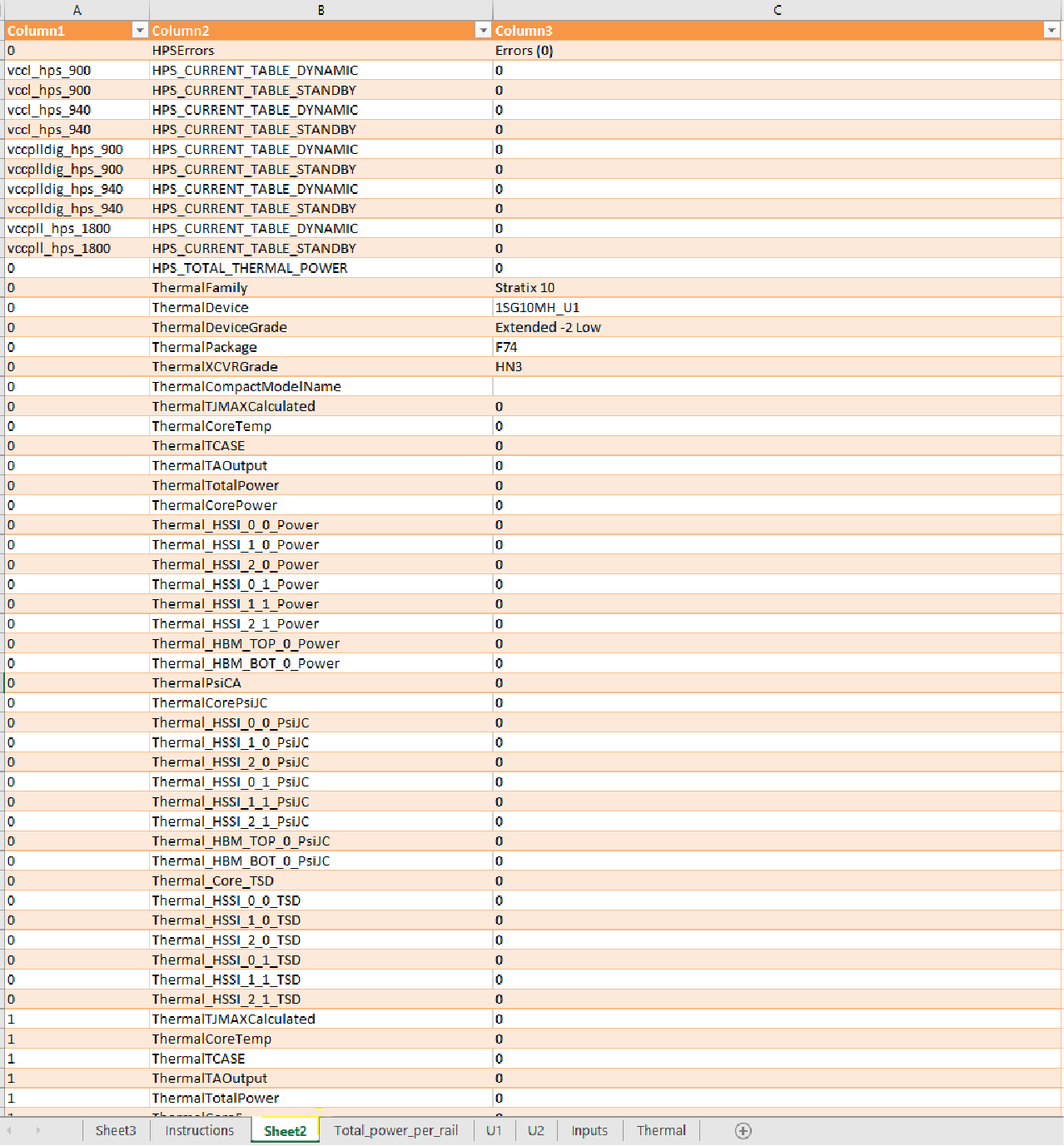 Figure 5. Content Copied into U1 Worksheet
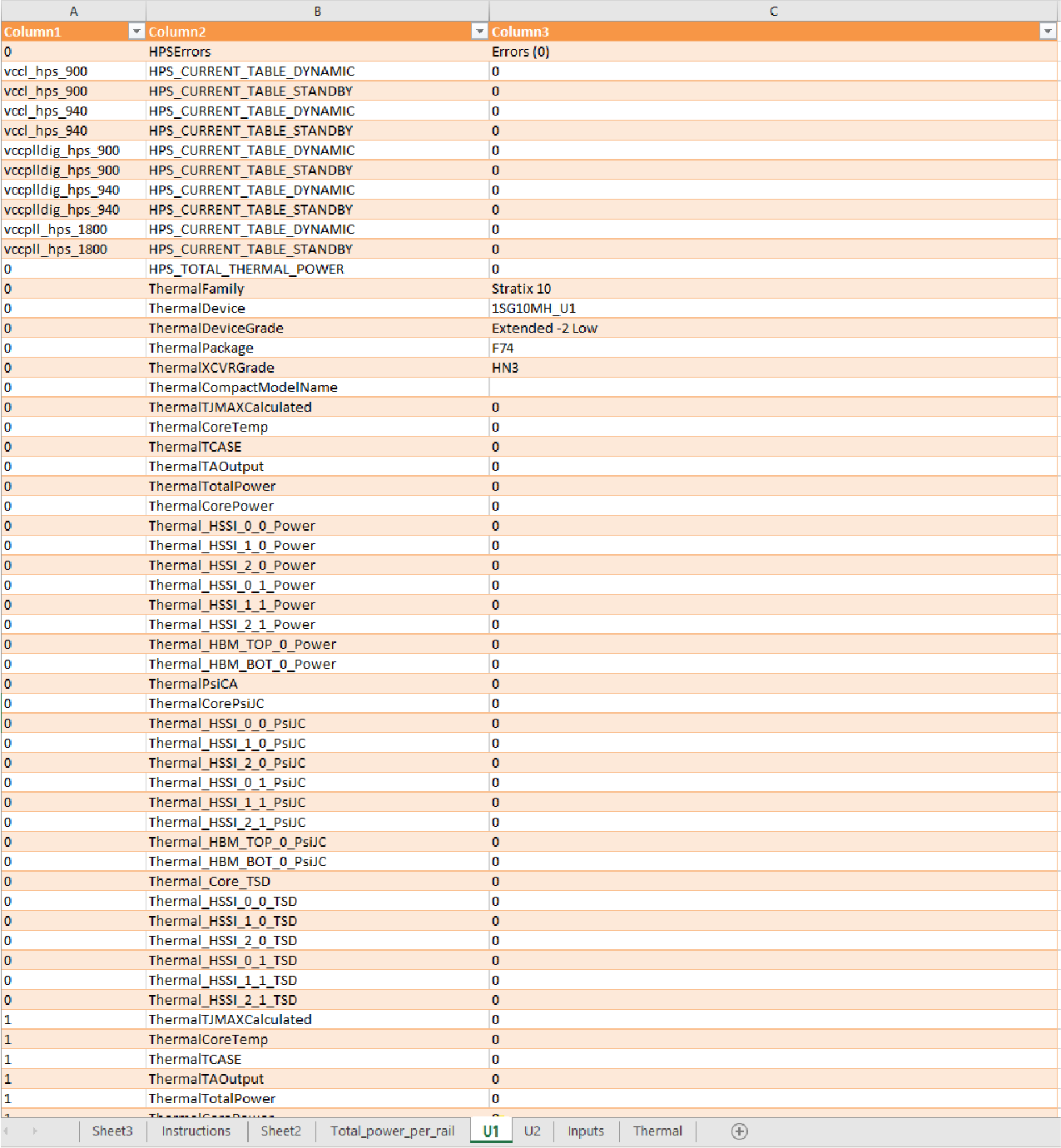
- Repeat the above steps for the U2 die.
Interpreting the Spreadsheet
- The Total_power_per_rail worksheet shows the power summary for both U1 and U1 — in this case, 1SG10M as a whole device).
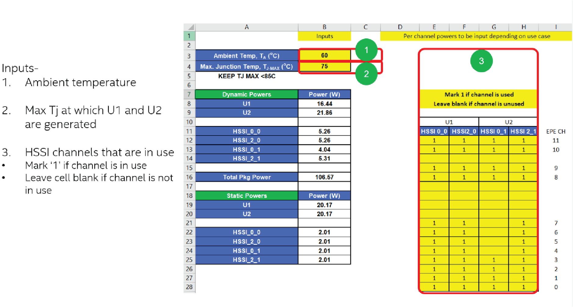
- On the Inputs worksheet, you need to provide the Ambient Temp, Max Junction Temp, TJ-MAX , and HSSI information.
Figure 6. Input Tab
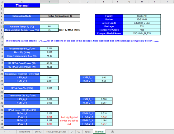
- The Thermal worksheet shows the summary for Ψ values and TSD offset values.
Figure 7. Thermal Worksheet