Visible to Intel only — GUID: pjr1582820927343
Ixiasoft
Visible to Intel only — GUID: pjr1582820927343
Ixiasoft
11.9.5.3. Data Pattern and Byte Enable
Example:
This example assumes the following conditions:
- DQ Width: x72 (without ECC enabled)
- Memory Protocol: DDR4
- DQ/DQS: 8
- Rate: Quarter-rate
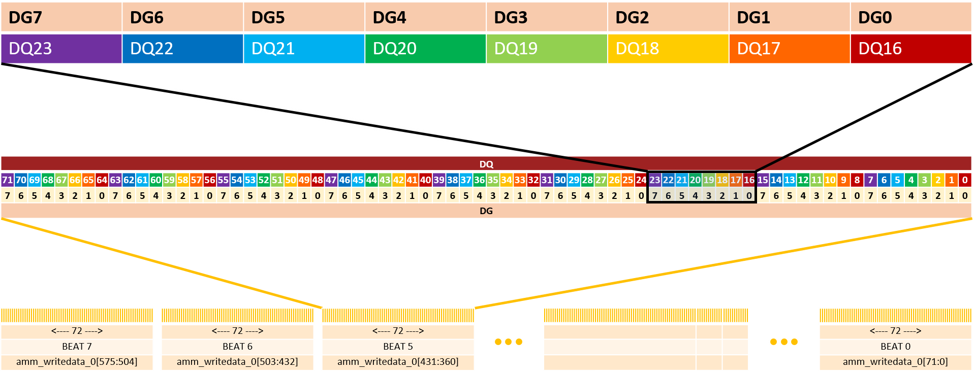
Because there are 8 DQ/DQS, there are 8 data generators, meaning that DQ0, DQ8, DQ16 … DQ56, and DQ64 share the same data generator.
In this example, each data transfer on the ctrl_amm interface is 576 bits wide. For the purpose of this example, we focus on beat 5 of the transfer, as seen on the memory side:
- DQ[0] corresponds to beat 5 of the memory bus burst and it takes bit5 from DG0
- DQ[1] corresponds to beat 5 of the memory bus burst and it takes bit5 from DG1
- ...
- DQ[3] corresponds to beat 5 of the memory bus burst and it takes bit5 from DG3
- ...
- DQ[8] corresponds to beat 5 of the memory bus burst and it takes bit5 from DG0
- DQ[9] corresponds to beat 5 of the memory bus burst and it takes bit5 from DG1

For each data generator, it is possible to configure a start seed (32 bits wide), and a pattern mode.
| Mode | Description |
|---|---|
| Fixed | The data pattern is constant. Only the lowest TG_DATA_RATE_WIDTH_RATIO bits are used – each one representing one beat on that pin. Example: A seed of 0x76543210 for DG0, where TG_DATA_RATE_WIDTH_RATIO=8 results in the following pattern seen on DQ0, sequentially: 
|
| PRBS7 | Pseudorandom Binary Sequence. Uses the 8 least-significant bits (LSB) of the input seed, and the monic polynomial: x7 + x6 + 1 A seed of ‘0 produces no unique patterns. |
| PRBS15 | Pseudorandom Binary Sequence. Uses the 16 least-significant bits of the input seed, and the monic polynomial: x15 + x14 + 1 A seed of ‘0 produces no unique patterns. |
| PRBS31 | Pseudorandom Binary Sequence. Uses all 32 bits of the input seed, and the monic polynomial: x31 + x28 + 1 A seed of ‘0 produces no unique patterns. |
| Rotating (custom) | The data pattern on the pin is 32 bits long, as specified by the user. The pattern appears on the pin least-significant bit to most-significant bit. Example: A seed of 0x76543210 for DG0 results in the following pattern seen on DQ0, sequentially: 
|
There is one byte-enable generator for each byte in the interface. The byte-enable generator options are identical to the data generator options.