Intel® Agilex™ Hard Processor System Remote System Update User Guide
A newer version of this document is available. Customers should click here to go to the newest version.
7.2.5. Creating the Initial Flash Image
Create an initial flash image containing the factory and application images and the associated RSU data structures.
- Start the Programming File Generator tool by running the qpfgw command:
cd $TOP_FOLDER ~/intelFPGA_pro/21.2/nios2eds/nios2_command_shell.sh \ qpfgw & - Select the Device family as Intel® Agilex™ , and Configuration mode as Active Serial x4.
- Change the Name to “initial_image”.
- Select the output file type as JTAG Indirect Configuration File (. jic ), which is the format used by the Intel® Quartus® Prime Programmer tool for writing to the QSPI flash.
- Select the optional Memory Map File (.map ) file so that it is also generated. The .map file contains information about the resulted flash layout.
- Select the optional Raw Programming Data File (.rpd ) file so that it is also generated. This file contains the binary flash content, without anything else added. The window looks similar to this:
- Click the Raw Programming Data File (.rpd ) file to select it. Then click the Edit ... button and select the Bitswap option to be "On". This enables the RPD file to be usable by HPS software like U-Boot and Linux if needed.
- Once the output type was selected, click the Input Files tab.
- In the Input Files tab click the Add Bitstream button, then browse to $TOP_FOLDER/hw/ghrd.0/output_files, select the file ghrd_agfb014r24a3e3vr0.sof, and then click Open. This is the initial factory image. Do the same for the $TOP_FOLDER/hw/ghrd.1/output_files/ghrd_agfb014r24a3e3vr0.sof image. This is the initial application image. The tab now looks like below:
- Click the first .sof file, then click the Properties button on the right side. This opens the window to browse for the FSBL and select authentication and encryption settings.
- Click the Bootloader … (Browse) button and select the file $TOP_FOLDER/u-boot-socfpga/spl/u-boot-spl-dtb.hex, then click OK.
- Click the second .sof file and add the same FSBL file to it. The Input Files tab now looks like shown below:
- Click the Configuration Device tab. Note that the tab is only enabled once at least one input file was added in the Input Files tab.
- Because more than one input file was added in the Input Files tab, it displays the options for remote system update. Otherwise, it only enables the standard configuration flow.
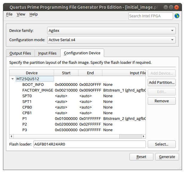
- In the Configuration Device tab, click Add Device, select the MT25QU02G in the dialog box window, then click OK. Once that is done, the window displays the default initial partitioning for RSU:
Note: You can also use another supported flash device, because this example only needs 512Mb of flash space. The Intel® Quartus® Prime Programmer displays some warnings in case another supported 512 Mb or larger flash is used, but the example works.
- Select the FACTORY_IMAGE entry, and click the Edit… button. The Edit Partition window pops up. Select the Input file as Bitstream_1 (ghrd_agfb014r24a3e3vr0.sof). Change Address Mode to Block because you want to make sure you are leaving enough space for the biggest factory image you anticipate using. Set the End Address to 0x0090FFFF in order to reserve 7MB for the factory image. This end address was calculated by adding 8MB to the end of the BOOT_INFO partition. Click OK.
Note: The Page property for FACTORY_IMAGE partition must always be set to 0. This means that the FACTORY_IMAGE can retry only after all the application images failed.
- Select the MT25QU02G flash device in the Configuration Device tab by clicking it, then click the Add Partition… button to open the Add Partition window. Leave the Name as P1 and select the Input file as Bitstream_2(ghrd_agfb014r24a3e3vr0.sof). This becomes the initial application image. Select the Page as 1 – this means it has the highest priority of all application images. Select the Address Mode as Block and allocate 16MB of data by setting Start Address = 0x01000000 and End Address = 0x01FFFFFF.
The Page property is used by the Programming File Generator to determine the order in which images appear initially in the configuration pointer block. The highest priority is the one with Page=1, then the one with Page=2, and so on. The Programming File Generator issues an error if there are multiple partitions with the same page number, or if there are any “gaps” as in having a Page=1 then a Page=3, without a Page=2 for example.
Only up to seven partitions can contain application images at initial flash image creation time. This limitation does not have adverse effects, as typically at creation time it is expected to have just a factory image and one application image.
- Create two more partitions P2 and P3 using the same procedure as for the previous step, except set the Input file to None, leave Page unchanged (it does not matter for empty partitions) and set the start and end addresses as follows:
- P2: Start Address = 0x02000000 and End Address = 0x02FFFFFF.
- P3: Start Address = 0x03000000 and End Address = 0x03FFFFFF.
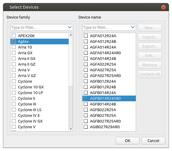
- Click Select … to select the Flash loader. The flash loader becomes part of the JIC file and is used by the Flash Programmer tool. Select the desired Device family and Device name as shown below:

The Configuration Device tab now looks like as shown below:

- Click File > Save As .. and save the file as $TOP_FOLDER/initial_image.pfg. This file can be useful later, if you wanted to re-generate the initial image by using the command:
cd $TOP_FOLDER
~/intelFPGA_pro/21.2/nios2eds/nios2_command_shell.sh \
quartus_pfg -c initial_image.pfg
Note: The created pfg file is actually an XML file which can be manually edited to replace the absolute file paths with relative file paths. You cannot directly edit the .pfg file for other purposes. The .pfg file can be opened from Programming File Generator, if changes are needed. - Click the Generate button to generate the initial flash image as $TOP_FOLDER/initial_image.jic and the map file as $TOP_FOLDER/initial_image_jic.map. A dialog box opens indicating the files were generated successfully.