Visible to Intel only — GUID: tch1547221325002
Ixiasoft
1. About the External Memory Interfaces Intel® Agilex™ 7 F-Series and I-Series FPGA IP
2. Design Example Quick Start Guide for External Memory Interfaces Intel® Agilex™ 7 F-Series and I-Series FPGA IP
3. Design Example Description for External Memory Interfaces Intel® Agilex™ 7 F-Series and I-Series FPGA IP
4. External Memory Interfaces Intel® Agilex™ 7 F-Series and I-Series FPGA IP Design Example User Guide Archives
5. Document Revision History for External Memory Interfaces Intel® Agilex™ 7 F-Series and I-Series FPGA IP Design Example User Guide
2.1. Creating an EMIF Project
2.2. Generating and Configuring the EMIF IP
2.3. Generating the Synthesizable EMIF Design Example
2.4. Generating the EMIF Design Example for Simulation
2.5. Simulation Versus Hardware Implementation
2.6. Simulating External Memory Interface IP With ModelSim
2.7. Pin Placement for Intel® Agilex™ 7 F-Series and I-Series EMIF IP
2.8. Compiling and Programming the Intel® Agilex™ 7 F-Series and I-Series EMIF Design Example
2.9. Generating a Design Example with the Calibration Debug Option
2.10. Generating a Design Example with the TG Configuration Option
2.11. Using the Design Example with the EMIF Debug Toolkit
Visible to Intel only — GUID: tch1547221325002
Ixiasoft
2.1. Creating an EMIF Project
For the Intel® Quartus® Prime software version 17.1 and later, you must create an Intel® Quartus® Prime project before generating the EMIF IP and design example.
- Launch the Intel® Quartus® Prime software and select File > New Project Wizard. Click Next.

- Specify a directory (<user project directory>), a name for the Intel® Quartus® Prime project (<user project name>), and a top-level design entity name (<user top-level instance name>) that you want to create. Click Next.

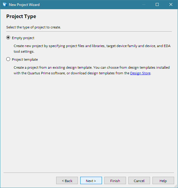
- Verify that Empty Project is selected. Click Next two times.

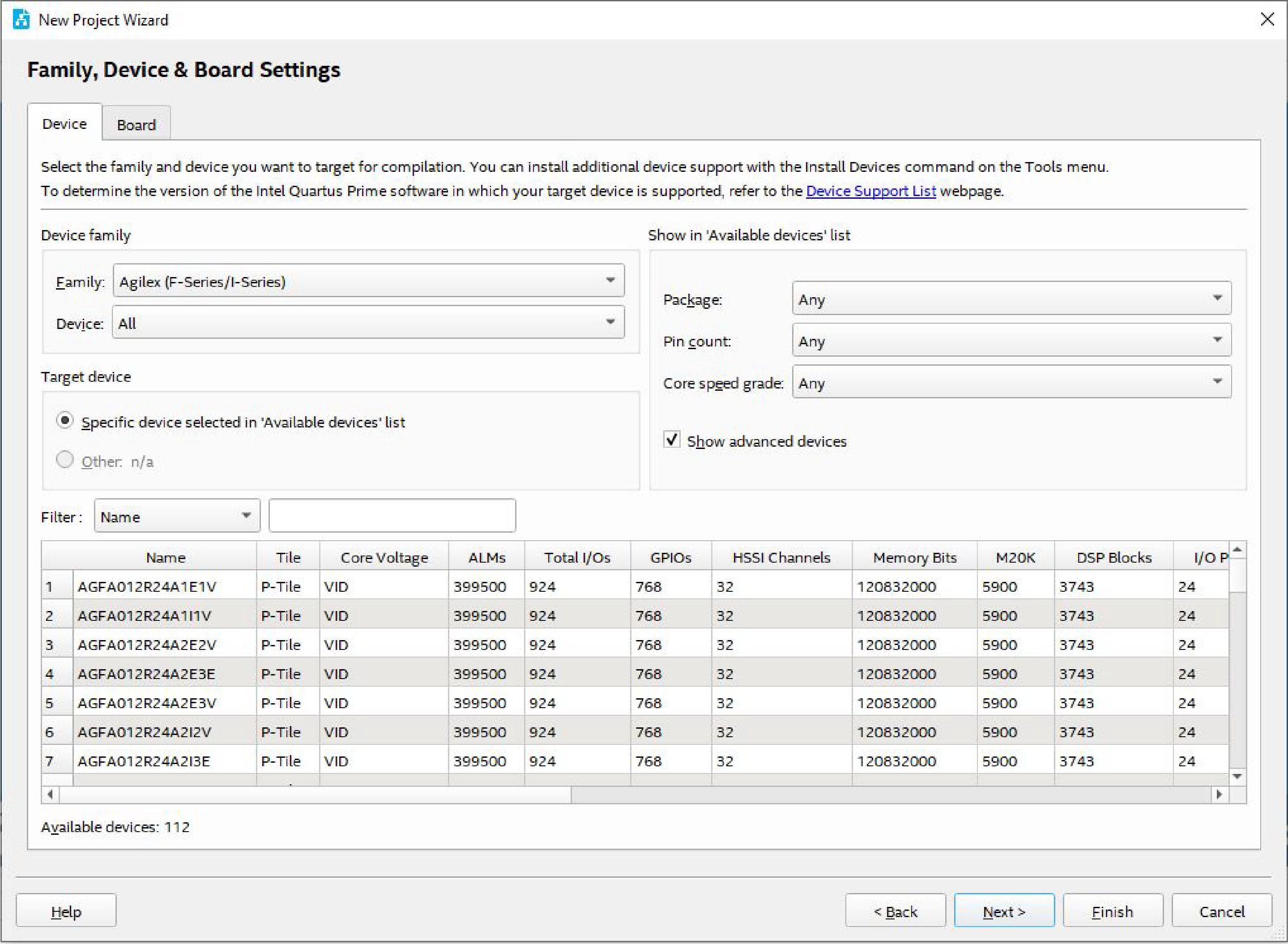
- Under Family, select Intel® Agilex™ 7.
- Under Name filter, type the device part number.
- Under Available devices, select the appropriate device.

- Click Finish.