Visible to Intel only — GUID: anr1547224889974
Ixiasoft
1. About the External Memory Interfaces Intel® Agilex™ 7 F-Series and I-Series FPGA IP
2. Design Example Quick Start Guide for External Memory Interfaces Intel® Agilex™ 7 F-Series and I-Series FPGA IP
3. Design Example Description for External Memory Interfaces Intel® Agilex™ 7 F-Series and I-Series FPGA IP
4. External Memory Interfaces Intel® Agilex™ 7 F-Series and I-Series FPGA IP Design Example User Guide Archives
5. Document Revision History for External Memory Interfaces Intel® Agilex™ 7 F-Series and I-Series FPGA IP Design Example User Guide
2.1. Creating an EMIF Project
2.2. Generating and Configuring the EMIF IP
2.3. Generating the Synthesizable EMIF Design Example
2.4. Generating the EMIF Design Example for Simulation
2.5. Simulation Versus Hardware Implementation
2.6. Simulating External Memory Interface IP With ModelSim
2.7. Pin Placement for Intel® Agilex™ 7 F-Series and I-Series EMIF IP
2.8. Compiling and Programming the Intel® Agilex™ 7 F-Series and I-Series EMIF Design Example
2.9. Generating a Design Example with the Calibration Debug Option
2.10. Generating a Design Example with the TG Configuration Option
2.11. Using the Design Example with the EMIF Debug Toolkit
Visible to Intel only — GUID: anr1547224889974
Ixiasoft
3.2. Simulation Design Example
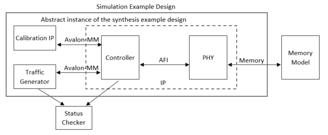
The simulation design example contains the major blocks shown in the following figure.
- An instance of the synthesis design example. As described in the previous section, the synthesis design example contains a traffic generator, calibration component, and an instance of the memory interface. These blocks default to abstract simulation models where appropriate for rapid simulation.
- A memory model, which acts as a generic model that adheres to the memory protocol specifications. Frequently, memory vendors provide simulation models for their specific memory components that you can download from their websites.
- A status checker, which monitors the status signals from the external memory interface IP and the traffic generator, to signal an overall pass or fail condition.
Figure 10. Simulation Design Example

