Report CDC Viewer Command
The Clock Domain Crossing (CDC) Viewer creates a graphical display which shows either setup, hold, recovery, or
removal analysis of all clock transfers in your design.
You open this report in the Timing Analyzer GUI by clicking in the Timing Analyzer. This creates a folder of CDC Viewer reports, containing one report for
each analysis type.

Report Panels
The reports consists of:
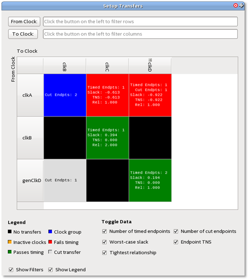
- Filter boxes for filtering From Clock: and To Clock: values. Clicking on the From Clock: or To Clock: opens the Name Finder dialog box.
- A color coded grid which displays the clock transfer status. Status colors are defined in the Legend.
- The clock headers list each clock with transfers in the design. If the name of the clock is too long, the display is truncated, but the full name can be seen in a tool tip or by resizing the clock header cell.
- Generated clocks are represented as children of the clock they are derived from. A '+' icon next to a clock name indicates there are generated clocks associated. Clicking on that clock header displays the generated clocks associated with that clock.
- A Legend and Toggle Data section for controlling the grid display output.
- You can use the Show Filters and Show Legend controls to turn Filters and Legend on or off.
Transfer Cell Content
Each block in the grid is referred to as a transfer cell. Each transfer cell uses color and text to display important details of the paths
involved in a transfer. The color coding represents the following states:
- Black—No transfers. There are no paths crossing between the source and destination clock of this cell.
- Green—Passes timing. All timing paths in this transfer, that have not been cut, meet their timing requirements.
- Red—Fails timing. One or more of the timing paths in the transfer do not meet their timing requirements. If the transfer is between unrelated clocks, the paths likely need to be synchronized by a synchronizer chain.
- Blue—Clock groups. The source and destination clocks of these transfers have been cut by means of asynchronous clock groups.
- Gray—Cut transfer. All paths in this transfer have been cut by false paths. The result of this is that these paths are not considered during timing analysis.
- Orange—Inactive clocks. One of the clocks involved in the transfer has been marked as an inactive clock (with the set_active_clocks command). Such transfers are ignored by the Timing Analyzer.
The text in each transfer cell contains data specific to each transfer. Types of data on display can be turned on or off with the Toggle Data boxes but you can mouse over any cell to see the full text. These data types are:
- Number of timed endpoints between clocks— The number of timed, endpoint-unique paths in the transfer. A path being “timed” means that it was analyzed during timing analysis. Only paths with unique endpoints count towards this total.
- Number of cut endpoints between clocks— The number of cut endpoint-unique paths, instead of timed ones. These paths have been cut by either a false path or clock group assignment. Such paths are skipped during timing analysis.
- Worst-case slack between clocks— The worst-case slack among all endpoint-unique paths in the transfer.
- Total negative slack between clocks— The sum of all negative slacks among all endpoint-unique paths in this transfer.
- Tightest relationship between clocks— The lowest-valued setup / hold / recovery / removal relationship between the two clocks in this transfer, depending on the analysis mode of the report
Transfer Cell Operations
Right-click menus allow you to perform operations on transfer cells and clock headers. When the operation is a Timing Analyzer report or SDC command, a dialog box opens prepopulated with the contents of the transfer cell.
Transfer cell operations include:
- Copy—Copies the contents of the transfer cell to the clipboard.
- Copy (include children)—Copies the name of the chose clock header, and the names of each of its derived clocks. This option only appears for clock headers with generated clocks.
- Report Timing—Not available for transfer cells with no valid paths (gray or black cells).
- Report Endpoints—Not available for transfer cells with no cut paths (gray or black cells).
- Report False Path—Not available for transfer cells with no valid paths (black cells).
- Report Exceptions
- Report Exceptions (with clock groups)—Only available for clock group transfers (blue cells)
- Set False Path
- Set Multicycle Path
- Set Min Delay
- Set Max Delay
- Set Clock Uncertainty
Clock header operations include:
- Copy—Copies the contents of the clock header to the clipboard.
- Expand/Collapse All Rows/Columns—Shows or hides all derived clocks in the grid.
- Create Slack Histogram—Generates a slack histogram report for the selected clock.
- Report Timing From/To Clock—Generates a timing report for the selected clock. If the clock has not been expanded to display its derived clocks, all clocks derived from the selected clock are included in the timing report as well. To prevent this, expand the clock before right-clicking it.
- Remove Clock(s)—Removes the selected clock from the design. If the clock has not been expanded, all clocks derived from the selected clock are also removed.
As with other Timing Analyzer reports, you may view CDC Viewer output in four formats:
- A report panel in the Timing Analyzer
- Output in the Timing Analyzer Tcl console
- A plain-text file
- An HTML file that can be viewed in a web browser.
The Timing Analyzer report panel is the recommended format.