Visible to Intel only — GUID: led1435796768662
Ixiasoft
Visible to Intel only — GUID: led1435796768662
Ixiasoft
2.9. Reset Polarity and Synchronization in Platform Designer
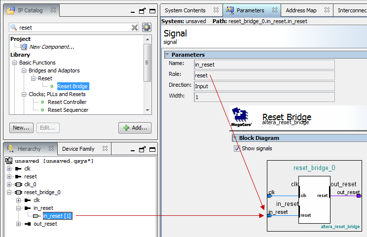
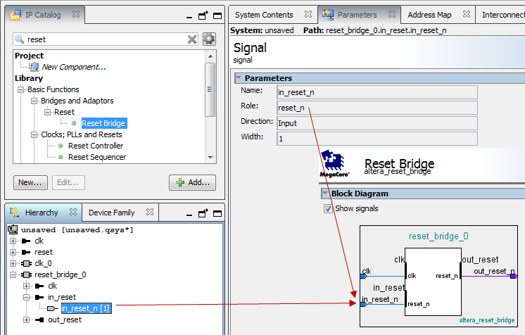
You can view the polarity status of a reset signal by selecting the signal in the Hierarchy tab, and then view its expanded definition in the open Parameters and Block Symbol tabs. When you generate your component, Platform Designer interconnect automatically inverts polarities as needed.
- None—There is no synchronization on this reset.
- Both—The reset is synchronously asserted and deasserted with respect to the input clock.
- Deassert—The reset is synchronously asserted with respect to the input clock, and asynchronously deasserted.
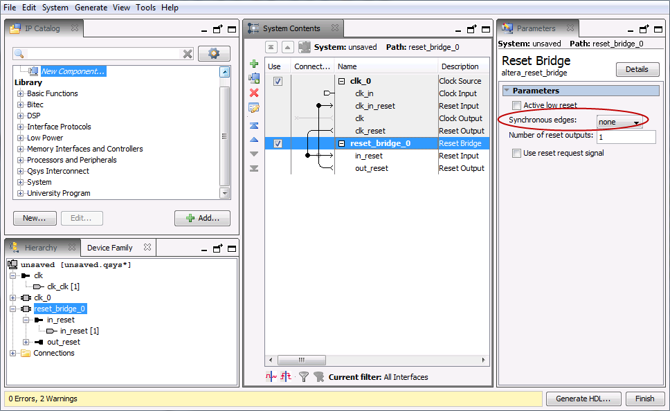
You can combine multiple reset sources to reset a particular component.
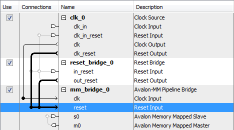
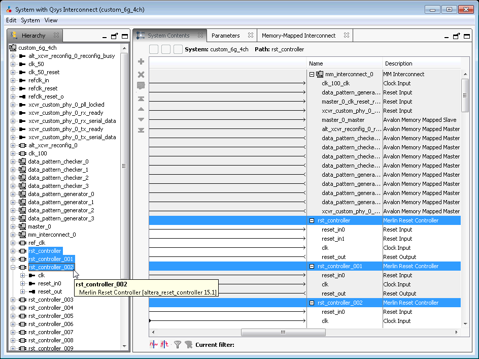
When you generate your component, Platform Designer inserts adapters to synchronize or invert resets if there are mismatches in polarity or synchronization between the source and destination. You can view inserted adapters on the Memory-Mapped Interconnect tab with the System > Show System with Platform Designer Interconnect command.
