Visible to Intel only — GUID: cmv1527848141403
Ixiasoft
Visible to Intel only — GUID: cmv1527848141403
Ixiasoft
7.9.1. Performing a Cosimulation
The design example has two HDL entities: the DPD (lut_dpd.vhd) and the FIR (complex_fir.vhd).
In DSP Builder cosimulation, each HDL Import block represents an HDL instance. You must instantiate both of these entities in a top-level VHDL file. For this design example, Intel provides top.vhd.
In addition, the FIR filter uses a signed data type with a generic for the data width. When DSP Builder instantiates the FIR filter, it uses its own paradigm (i.e. std_logic_vector and no generics). This design example adds a wrapper entity: complex_fir_wrapper.vhd. This entity instantiates complex_fir, including setting the generic to the appropriate value, and converts signed to std_logic_vector.
These two files, top.vhd and complex_fir_wrapper.vhd are in the to_import directory.
Procedure
- Add a HDL Import Config block to the top-level design.
Figure 71. Top-level Design with HDL Import Config Block

- Parameterize the HDL Import Config block.
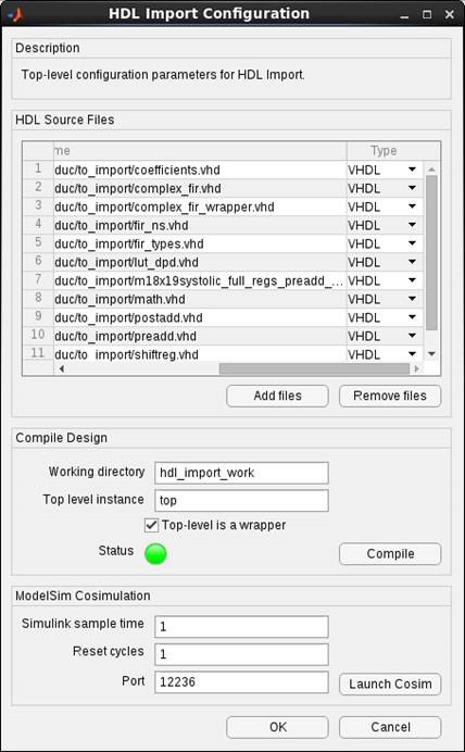
- Click Add to add all of the files from the to_import directory.
The order of the files does not matter. DSP Builder determines the type of HDL file by the extension, but you can change the type manually.
- Enter top in the Top level instance.
- Turn on Top-level is a wrapper.
- Click the Compile button.
- Set the Simulink sample time field to 1.
- When the status light is green, click Launch Cosim.
Figure 72. HDL Import Configuration
- Click Add to add all of the files from the to_import directory.
- Add a HDL Import block to the digital_up_converter subsystem.
- Double click the HDL Import block
- Click Instance and select inst_fir.
- Set the fractional bits of the two output signals to 16.
Figure 73. HDL Import Block inst_fir Parameters

- Add a second HDL Import block to the digital_up_converter subsystem.
- Double click the HDL Import block
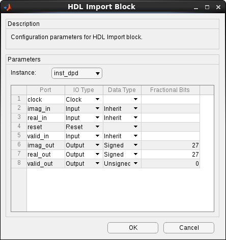
- Click Instance and select inst_dpd.
- Set the fractional bits of the two output signals to 27.
- Set the valid output to unsigned.
Figure 74. HDL Import inst_dpd Parameters
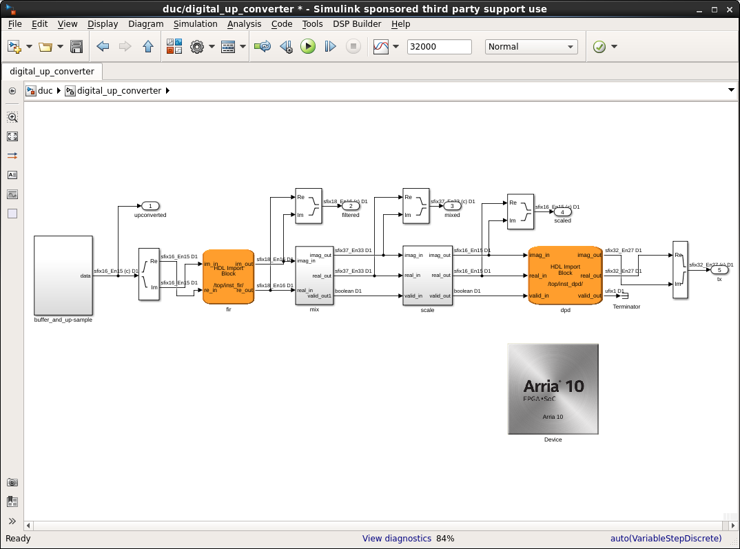
- Wire up HDL import blocks.
The HDL Import block port names are in alphabetical order.Figure 75. Wire up HDL Import Blocks

- Press the play button or advance through the simulation a cycle at a time.
- Verify HDL import with the ModelSim simulator, in DSP Builder, select DSP Builder > Run ModelSim > Device.
The cosimulation turns any non-high state (e.g. U or X) to a zero.
- Compile the design in Intel® Quartus® Prime, by selecting DSP Builder > Run Quartus Prime Software.