Visible to Intel only — GUID: mwh1442946322464
Ixiasoft
2.3.1. Recommended Initial SDC Constraints
2.3.2. SDC File Precedence
2.3.3. Iterative Constraint Modification
2.3.4. Creating Clocks and Clock Constraints
2.3.5. Creating I/O Constraints
2.3.6. Creating Delay and Skew Constraints
2.3.7. Creating Timing Exceptions
2.3.8. Example Circuit and SDC File
2.3.7.5.1. Default Multicycle Analysis
2.3.7.5.2. End Multicycle Setup = 2 and End Multicycle Hold = 0
2.3.7.5.3. End Multicycle Setup = 2 and End Multicycle Hold = 1
2.3.7.5.4. Same Frequency Clocks with Destination Clock Offset
2.3.7.5.5. Destination Clock Frequency is a Multiple of the Source Clock Frequency
2.3.7.5.6. Destination Clock Frequency is a Multiple of the Source Clock Frequency with an Offset
2.3.7.5.7. Source Clock Frequency is a Multiple of the Destination Clock Frequency
2.3.7.5.8. Source Clock Frequency is a Multiple of the Destination Clock Frequency with an Offset
Visible to Intel only — GUID: mwh1442946322464
Ixiasoft
2.3.6.4. Create Timing Netlist
You can configure or load the timing netlist that the Timing Analyzer uses to calculate path delay data.
You must generate the timing netlist before running timing analysis. You can use the Create Timing Netlist dialog box or the Create Timing Netlist command in the Tasks pane. Create Timing Netlist also generates Advanced I/O Timing reports if you turn on Enable Advanced I/O Timing in the Timing Analyzer page of the Settings dialog box.
Note: The Compiler creates the timing netlist during compilation. The timing netlist does not reflect any configuration changes that occur after the device enters user mode, such as dynamic transceiver reconfiguration. This applies to all device families except transceivers on Intel® Arria® 10 devices with the Multiple Reconfiguration Profiles feature.
The following diagram shows how the Timing Analyzer interprets and classifies timing netlist data for a sample design.
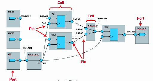
Figure 57. How Timing Analyzer Interprets the Timing Netlist