Steps to install PCIe* add-in card on Intel® Server D50DNP PCIe* Accelerator Module (D50DNP2MFALAC)
How to install PCIe* add-in card on Intel® Server D50DNP accelerator module.
The PCIe* accelerator module includes a special riser assembly that can support up to four x16 full-height, full-length, double-width PCIe* add-in cards for acceleration solutions. The PCIe* accelerator module riser assembly is on the right side of the module.
Required Tools and Supplies:
- Phillips* head screwdriver #1
- Anti-static wrist strap and conductive workbench pad (recommended)
- PCIe* accelerator add-in card
- PCIe* accelerator module card Kit matching the card type
Follow the below steps to install PCIe* accelerator card:
Note | The following steps to replace the accelerator add-in card metal bracket should be performed along with the instructions in the add-in card documentation. |
- Remove the screws that hold the original metal bracket on the accelerator add-in card (see Letter A).
- Uninstall the original metal bracket (see Letter B) and replace it with the metal bracket in the accessory kit (see Letter C).
- Fasten the screws to secure the metal bracket to the accelerator add-in card (see Letter D).
- If the accessory kit comes with the rear extension bracket, install it on the accelerator add-in card.
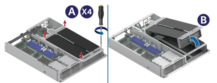
- Using Phillips* head screwdriver #1, loosen the four captive screws on the PCIe* accelerator module riser assembly (see Letter A).
- Carefully lift the PCIe* accelerator module riser assembly up about two inches. Then, tilt the front side away from the module (see Letter B).
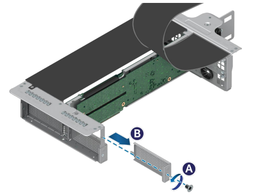
- Remove the screw holding the flap on the front side of the riser assembly and lift the flap up.
- Remove the screw holding the original metal bracket (see Letter A) and remove the bracket from the front side of the riser assembly (see Letter B).
- If the bracket kit includes a power cable, attach it to the accelerator add-in card.
- Align the bracket of the accelerator add-in card with the opening of the riser assembly.
- Route the add-in card power cable through the plastic shield opening in the rear of the riser assembly.
- Carefully push the add-in card into the PCIe* slot (see Letter A). Ensure that the card is fully seated.
- Fasten the screw on the metal bracket to secure the add-in card to the riser assembly (see Letter B).
- Fasten the two screws on each corner of the back end to attach the accelerator add-in card to the riser assembly.
- Repeat steps 1 through 14 to install other accelerator card as needed.
- Install the screw that holds the flap on the front side of the riser assembly.
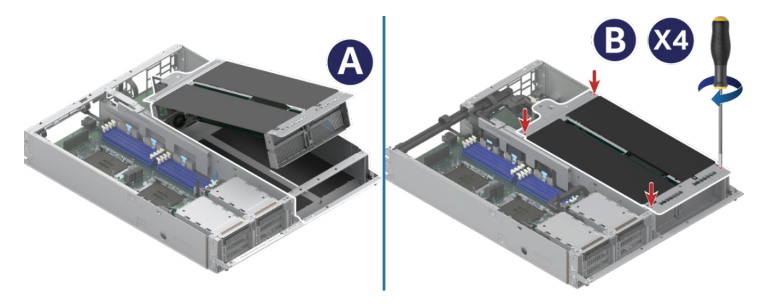
- Install the PCIe* accelerator module riser assembly by tilting the front side down to the module (see Letter A).
- Using Phillips* head screwdriver #1, fasten the captive screws to secure the PCIe* accelerator module riser assembly to the module (see Letter B)
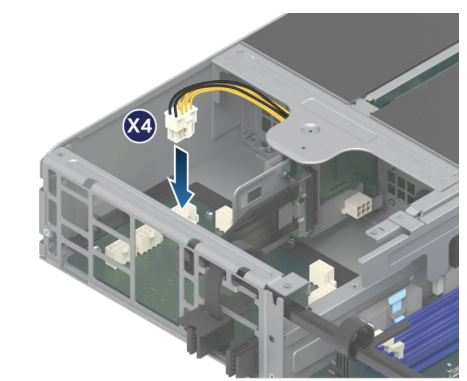
- Connect all accelerator power cables to the connectors on the power board.