Required Tools and Supplies
- Intel® Server Board M50FCP2SBSTD spare
- Anti-static wrist strap and conductive workbench pad (recommended)
- Phillips* head screwdriver #2
Server Board Removal
- Power off the system and remove power cords from each power supply module installed.
- Disconnect all externally attached cables.
- Remove the system top cover (see Section 6.5.1).
- Remove power supply modules (see Section 6.4).
- Remove all system fans (see Section 6.2).
- Disconnect all internal cables attached to PCIe* add-in cards.
- Remove riser card assemblies (see Section 6.6).
- If present, remove the OCP add-in card
- If present, remove all options installed onto the server board, including: TPM Module and M.2 SSDs
- Remove processors (see Section 6.5.1).
- Remove all memory modules and DIMM blanks (see Section 6.3).
- Disconnect all cables attached to connectors on the server board.
- Detach the two metal air baffles attached to the left and right edges of the server board and carefully lift the air baffles attached on both PSU bays up and away.
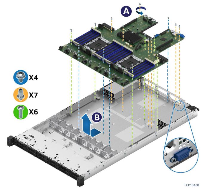
- Remove all fasteners used to secure the server board to the chassis (see Letter ‘A’).
- Slide the server board towards the front of the chassis to disengage all external connectors from the chassis cut-outs on the chassis back panel.
- Carefully lift the server board from the chassis and place it into an anti-static bag.
- Verify that all cables are clear of the board placement target within the chassis.
- Locate and carefully remove the server board from its anti-static bag. Hold the server board by its edges. Do not touch any components on the server board.
Server Board Installation
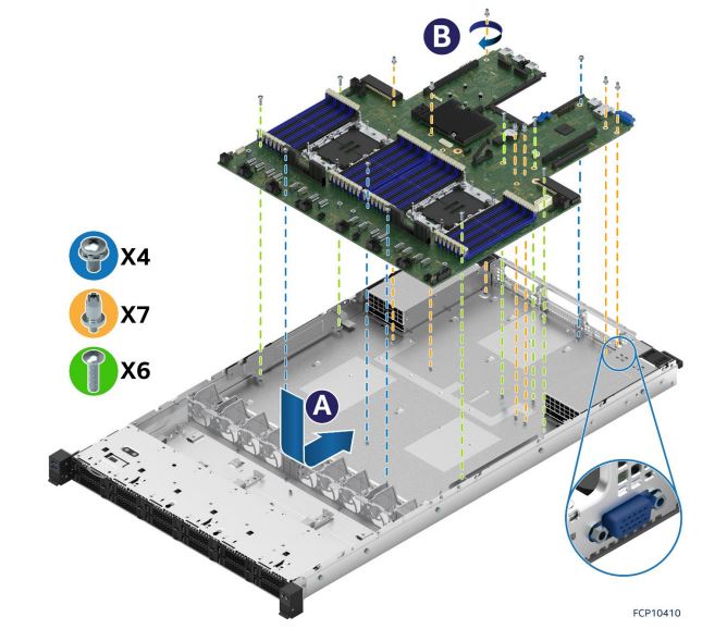
- Carefully lower the server board into the chassis.
- Slide the server board towards the back of the chassis until all external connectors on the back edge of the server board are in place with the cut outs on the chassis back panel.
- Verify that all screw holes align with the chassis standoffs (see Letter A).
- Secure the server board to the chassis using all the fasteners removed in Step 14. (See Letter B), tighten to 5 in-lb.
- Place and secure the right and left metal air baffles to the edges of the server board. Tighten to 5 in-lb. Lower the air baffles attached on both PSU bays to the server board.
- Re-attach all cables previously disconnected from the server board.
- Reinstall processors (see Section 6.5.3).
- Reinstall memory modules and DIMM blanks (see Section 6.3).
- Reinstall all options previously removed from the server board.
- Reinstall riser card assemblies (see Section 6.6).
- Re-attach all internal cables previously detached from PCIe* add-in cards. See Section 3.2 for cable routing.
- Reinstall all system fans (see Section 6.2).
- Reinstall power supply modules (see Section 6.4).
- Reinstall the system top cover (see Section 6.5.2).