Processor Support for Intel® Server M50FCP Family
The Intel® Server M50FCP Family includes two Socket-E LGA4677 processor sockets compatible with the 4th Generation Intel® Xeon® Scalable Processor family.
This article provides information on processor heat sinks, thermal design power (TDP), and population rules, including a processor family overview.
| Note | Previous-generation Intel® Xeon® Processors and Intel® Xeon® Scalable Processor families and their supported processor heat sinks are not compatible with server boards described in this document. |
Processor Family Overview
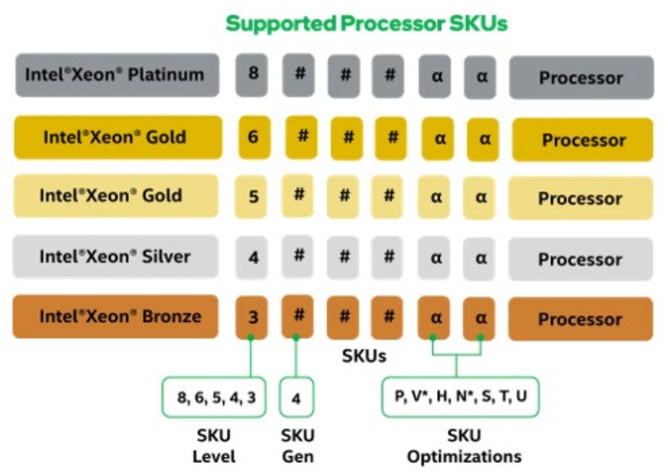
Supported processor SKUs for this Intel® server product family can be identified as follows:
Intel® Xeon® Platinum 84xxxx
Intel® Xeon® Gold 64xxxx
Intel® Xeon® Gold 54xxxx
Intel® Xeon® Silver 44xxxx
Intel® Xeon® Bronze 34xxxx
The following figure illustrates how to identify supported processor SKUs.
| Note |
|
4th Gen Intel® Xeon® Scalable Processor Family Feature Comparison
| Feature | Platinum 8xxx Processors | Gold 6xxx Processors | Gold 5xxx Processors | Silver 4xxx Processors |
| # of Intel® UPI Links | 3 | 3 | 3 | 2 |
| Intel® UPI Speed | 16 GT/s | 16 GT/s | 16 GT/s | 16 GT/s |
| Supported Topologies | 2S-2UPI 2S-3UPI | 2S-2UPI 2S-3UPI | 2S-2UPI 2S-3UPI | 2S-2UPI |
| Node Controller Support | No | No | No | No |
| RAS Capability | Advanced | Advanced | Advanced | Standard |
| Intel® Turbo Boost Technology | Yes | Yes | Yes | Yes |
| Intel® Hyper-Threading Technology (Intel® HT Technology) | Yes | Yes | Yes | Yes |
| Intel® Advanced Vector Extensions 512 (Intel® AVX-512) ISA Support | Yes | Yes | Yes | Yes |
| Intel® AVX-512 - # of 512b FMA Units | 2 | 2 | 1 | 2 |
| # of PCIe* Lanes | 80 | 80 | 80 | 80 |
| Intel® Volume Management Device (Intel® VMD) | Yes | Yes | Yes | Yes |
| Note | Features may vary between processor SKUs |
Supported Technologies
The 4th Gen Intel® Xeon® Scalable processors combine several key system components into a single processor package including the processor cores, Integrated Memory Controllers (IMCs), and Integrated IO Module.
The core features and technologies for the processor family include:
- Intel® Ultra Path Interconnect (Intel® UPI): supports up to 16 GT/s
- Intel® Speed Shift Technology
- Intel® 64 architecture
- Enhanced Intel® SpeedStep® Technology
- Intel® Turbo Boost Technology 2.0
- Intel® Hyper-Threading Technology (Intel® HT Technology)
- Intel® Virtualization Technology (Intel® VT) for IA-32, Intel® 64 and Intel® Architecture (Intel® VT-x)
- Intel® Virtualization Technology (Intel® VT) for Directed I/O (Intel® VT-d)
- Execute Disable Bit
- Intel® Trusted Execution Technology (Intel® TXT)
- Intel® Advanced Vector Extensions (Intel® AVX-512)
- Intel® Advanced Encryption Standard New Instructions (Intel® AES-NI)
- Intel® Deep Learning Boost (Intel® DL Boost) through VNNI
- Intel® Speed Select Technology (Intel® SST) on select processor SKUs
- Intel® Resource Director Technology (Intel® RDT)
Processor Heat Sink Module (PHM) Overview
The server board includes two processor socket assemblies, each consisting of a processor socket and bolster plate. The factory installed bolster plate is secured to the server board and is generally used to align
the processor cooling hardware over the processor socket and secure it to the server board.
Processor cooling options in a server system may use a passive or active heat sink that use airflow to dissipate heat generated by the processors. Other processor cooling options may use liquid cooling plates,
where cool liquid is pumped through the cooling plates to absorb and evacuate the heat from the processor. For air cooled systems. the processor and heat sink are generally pre-assembled into a single Processor
Heat-sink Module (PHM) before being installed onto the processor socket assembly. The PHM concept reduces the risk of damaging pins within the processor socket during the processor installation process.
| Note | The Intel® Server M50FCP Family only supports passive air-cooled options |
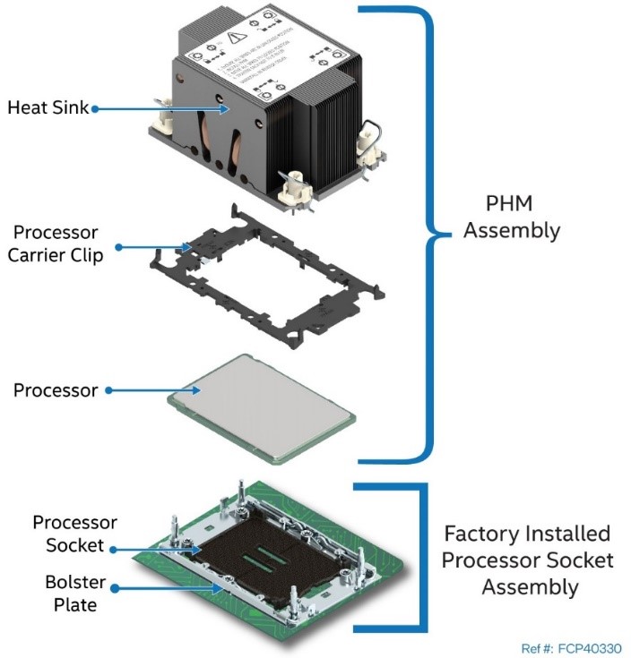
A PHM assembly consists of a processor, a processor carrier clip, and the processor heat sink. The following figure identifies each component associated with the PHM and processor socket assembly.
 |
| PHM Components and Processor Socket Reference Diagram |
| Note | Figure above is intended as a general reference to components that make up the PHM and processor socket assemblies. The components shown may or may not match exactly what may be used. The diagram |
Processor Carrier Clips
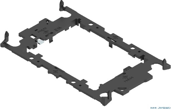
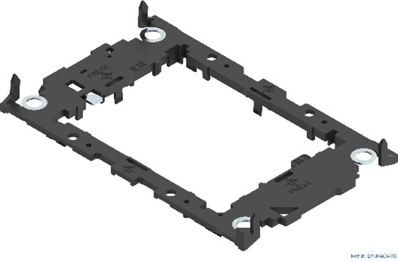
There are two types of processor carrier clips supported by the 4th Gen Intel® Xeon® Scalable processor family for this server product family, they are identified as E1A and E1B.
 |  |
| Supported Processor Carrier Clips | |
Each type of processor carrier clip will include identifier markings as shown in Figure below. The selected processor SKU determines which processor clip to use when assembling the processor heat
sink module (PHM). A processor carrier clip identifier marking will be etched onto the processor heat spreader as shown in Figure below
| Processor Carrier Clip Identifier Markings |
| Note | The etched identifier location in the figure above is for illustration purposes only. The actual location and color may be different on the actual processor and carrier clip |
Disclaimer: Intel® server boards contain and support several high-density VLSI and power delivery components that need adequate airflow to cool and remain within their thermal operating limits. Intel
ensures through its own chassis development and testing that when an Intel server board and Intel chassis are used together, the fully integrated system meets the thermal requirements of these components. It is the responsibility of the system architect or system integrator who chooses to develop their own server system using an Intel server board and a non-Intel chassis, to consult relevant specifications and datasheets to determine thermal operating limits and necessary airflow to support intended system configurations and workloads when the system is operating within target ambient temperature limits. It is also their responsibility to perform adequate environmental validation testing to ensure reliable system operation. Intel cannot be held responsible if components fail or the server board does not operate correctly when published operating and non-operating limits are exceeded.
Processor Cooling Requirements
For the server system to support optimal operation and long-term reliability, the thermal management solution of the selected server chassis must dissipate enough heat generated from within the chassis to keep the processors and other system components within their specified thermal limits. For optimal operation and long-term reliability, processors in the 4th Gen Intel® Xeon® Scalable processor family must operate within their defined minimum and maximum case temperature (TCASE) limits. See the 4th Gen Intel® Xeon® Processor Scalable Family Thermal Mechanical Specifications and Design Guide for additional information concerning processor thermal limits.
| Note | It is the responsibility of the system and components architects to ensure compliance with the processor thermal specifications. Compromising processor thermal requirements impacts the processor performance and reliability. |
Processor Thermal Design Power (TDP)
The Intel® Server Board M50FCP2SBSTD supports the 4th Gen Intel® Xeon® Scalable processor family with a maximum thermal design power (TDP) limit of 350 W
| Note | The maximum supported processor TDP at the system level may be lower than what the server board can support. Supported power, thermal, and configuration limits of the chosen server chassis / system need |
Processor Population Rules
| Note | The server board may support dual-processor configurations consisting of different processors that meet the following defined criteria. However, Intel does not perform validation testing of this configuration. |
When using a single processor configuration, the processor must be installed in the processor socket labeled CPU_0.
| Note | Some server board features may not be functional unless a second processor is installed. For the Intel® Server Board M50FCP2SBSTD, see Server Board Architecture Overview on Technical Product Specification document. |
When two processors are installed, the following population rules apply:
- Both processors must have identical extended family, extended model number and processor type
Also:
- Both processors must have the same number of cores.
- Both processors must have the same cache sizes for all levels of processor cache memory.
- Both processors must support identical DDR5 memory frequencies.
| Note | Processors with different steppings can be mixed in a system if the rules mentioned in the above bullets are met. |
Population rules are applicable to any combination of processors in the 4th Gen Intel® Xeon® Scalable processor family