Environment
Operating System
Description
Unable to determine if using only one CPU opens up all PCIe* lanes on the S2600WFTR board.
Resolution
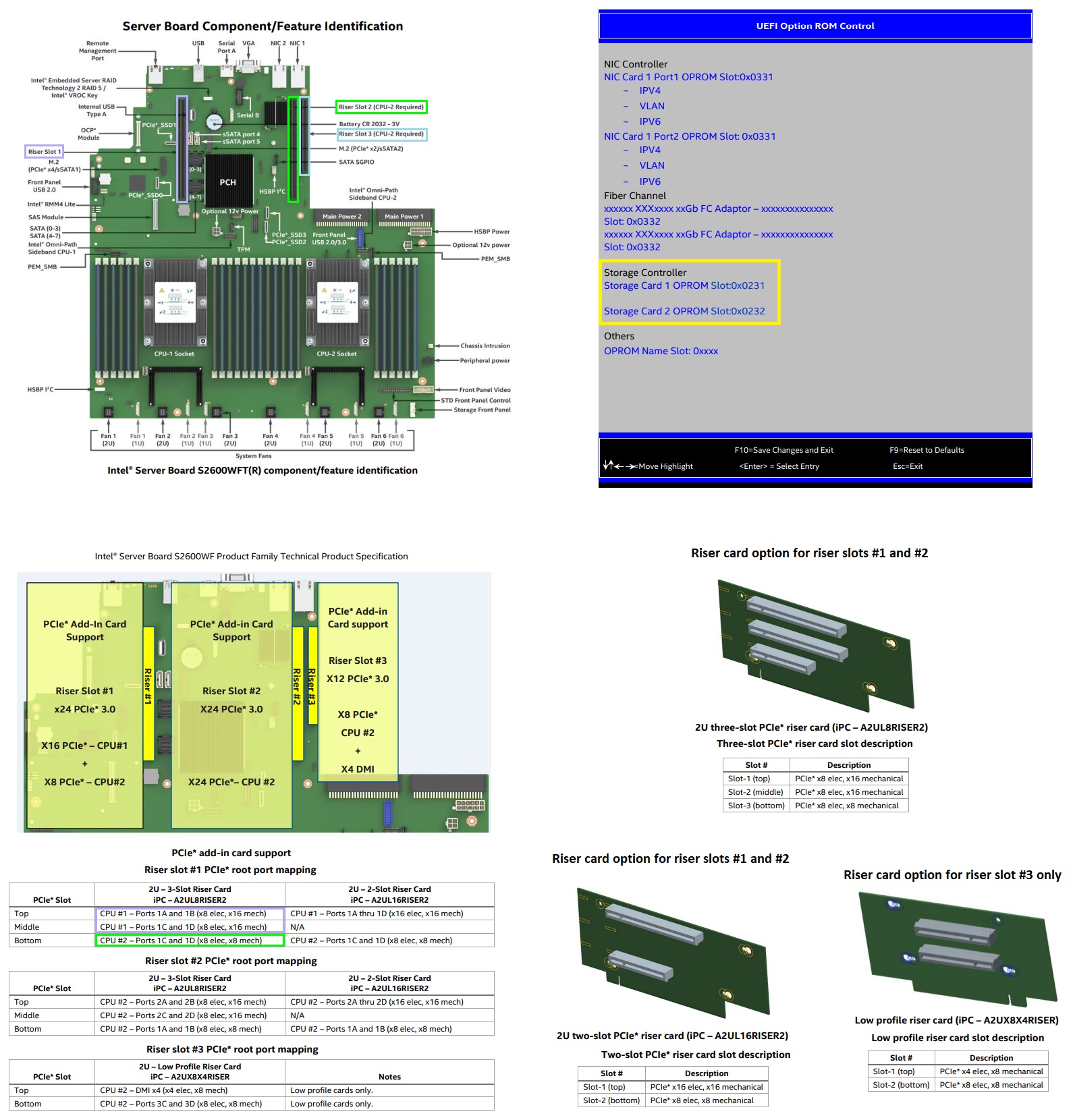
The server board provides three riser card slots identified as: Riser Slot #1, Riser Slot #2, and Riser Slot #3. The PCIe bus lanes for each riser card slot is supported by each of the two installed processors.
- Riser Slot #1: X24 PCIe* 3.0
- X16 PCIe* - CPU #1
- X8 PCIe* - CPU #2
- Riser Slot #2: X24 PCIe* 3.0
- X24 PCIe* - CPU #2
- Riser Slot #3: X12 PCIe* 3.0
- X8 PCIe* - CPU #2
- X4 PCIe* - DMI
Note: A dual processor configuration is required when using Riser Slot #2 and Riser Slot #3, as well as the bottom add-in card slot for 2U riser cards installed in Riser Slot #1.
Figure below show this information:

Additional information
Riser slot root port mapping for Intel® Server Board S2600WF can be found in the Technical Product Specification, section named PCIe* Add-in Card Support.
Riser cards for the Intel® Server Board S2600WF can be found at Configuration Guide, section named 1U/2U PCIe* Riser Card Accessory/Spare FRU Options table named 2U riser card options.
Location within the system BIOS of the Intel® Server Board S2600WF where the RAID controller card must appear can be found at BIOS Setup Utility User Guide for the Intel® Server Board S2600 Family Supporting the Intel® Xeon Scalable Processor Family, section named UEFI Option ROM Control.