Environment
Description
Unable to determine which mode and PCIe* port needs to be connected, since the server is not detecting it with one processor configuration
Resolution
Section named PCIe* Add-in Card Support describes which PCIe* 3.0 is controlled by each processor
Use the PCIe 3.0 Port #5 or #6 since they are handled by CPU #1 and the server will be able to detect the add-in card with one processor installed only.
Use the PCIe 3.0 Port #1 to #4 since they are handled by CPU #2 and the server will be able to detect the add-in card with the two processors installed.
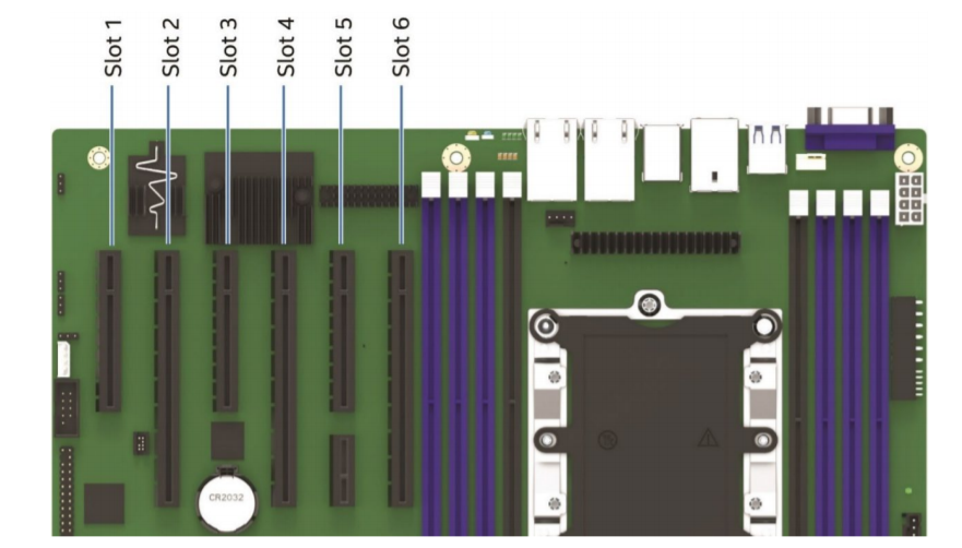
- Slot 1: PCIe* 3.0 x8 (x8 electrical) handled by CPU2
- Slot 2: PCIe* 3.0 x16 (x16 electrical) handled by CPU2 (riser capable)
- Slot 3: PCIe* 3.0 x8 (x8 electrical) handled by CPU2
- Slot 4: PCIe* 3.0 x16 (x16 electrical) handled by CPU2
- Slot 5: PCIe* 3.0 x8 (x8 electrical) handled by CPU1
- Slot 6: PCIe* 3.0 x16 (x16 electrical) handled by CPU1 (riser capable)
Figure Image to locate the PCIe* ports and its respecting number:
Additionally, section named Riser Card Support
PCIe* slots 2 and 6 are both capable of supporting riser cards. Each x16 riser slot supports standard x16 PCIe* connector Pin-outs, and they also include two 100-Mhz clocks and Riser_ID bits (to provide link width information to the system BIOS). Each of the designated riser slots can support riser cards with the following PCIe* add-in card slot configurations:
- x16 riser with two x4 PCIe* slots
- x16 riser with one x4 PCIe* slot and one x8 PCIe* slot
- x16 riser with two x8 PCIe* slots
- x16 riser with one x16 PCIe* slot
| Note | For compatible list of PCIe cards, please refer to Intel S2600ST Product Family Configuration Guide |
Additional information
Related topic:
S2600STBR Technical Product Specification on section 6.2 "PCIe Add-in Card Support"