Quick Start User's Guide for Intel® Server Board S3200SHV/S3210SHLC
Content Type: Install & Setup | Article ID: 000007299 | Last Reviewed: 01/08/2021
Intel® Server Board S3200SHV/S3210SHLC quick start user’s guide
| Note | For information on the front panel header for the Intel® Server Board S3200SH family |
Beginning
Integration
Reference
The Intel® Server Board S3200SHV / S3210SHLC is supported in the Intel® Entry Server Chassis SC5299-E.
Read all cautions and warnings first before starting your server system integration.
![]() Warning: Read all caution and safety statements in this document before performing any of the instructions. Also see the Intel® Server Board Safety Information document for complete safety information.
Warning: Read all caution and safety statements in this document before performing any of the instructions. Also see the Intel® Server Board Safety Information document for complete safety information.
![]() Warning: Installation and service of these products should only be performed by qualified service personnel to avoid risk of injury from electrical shock or energy hazard.
Warning: Installation and service of these products should only be performed by qualified service personnel to avoid risk of injury from electrical shock or energy hazard.
![]() Caution: Observe normal ESD [Electrostatic Discharge] procedures during system integration to avoid possible damage to server board and/or other components.
Caution: Observe normal ESD [Electrostatic Discharge] procedures during system integration to avoid possible damage to server board and/or other components.
Anti-static wrist strap
#2 Phillips* screwdriver

To avoid integration difficulties and possible board damage, your system must meet the following minimum requirements:
Preparing the chassis
When using an Intel® Server Chassis, begin with the Quick Start User’s Guide that came with your chassis. Return to this document when directed by the server chassis Quick Start User’s Guide. If using a non-Intel® server chassis, refer to the documentation that came with your chassis for preparatory steps.
Observe normal Electrostatic Discharge (ESD) procedures. Place your Intel® Server Chassis on a flat anti-static surface to perform the following integration procedures. Always touch the chassis frame first before reaching inside to make server board connections or to install components.
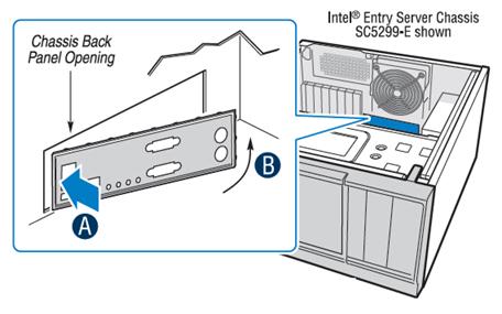
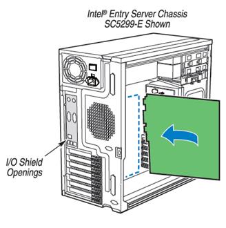
Install the I/O shield
Shield installs from inside of chassis. The labels should be visible from the outside of the chassis.
Install the server board
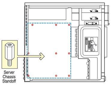
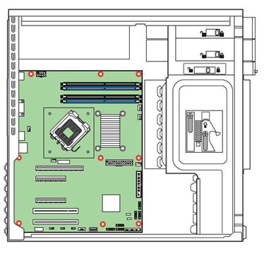
Install the standoffs
Nine standoffs must be installed into the chassis before installing the server board. Locate the threaded standoff holes that match the server board, and install a standoff at each location indicated by the RED circles [![]() ].
].
| Note | Verify that each server board mounting hole location has an installed standoff. Do not install a standoff at a location that does not have a corresponding server board mounting hole. |
Insert the server board
Place the board into the chassis, making sure that back panel I/O ports and chassis or I/O shield openings align correctly. Verify that server board mounting holes align correctly with the chassis standoffs.
When using the Intel® Entry Server Chassis SC5299-E, insert the I/O connector side [back] of the board first.
Attach the server board
| Note | Intel® Entry Server Chassis and a non-Intel chassis may use different fasteners to attach the server board to the chassis. Use the fasteners that came with your chassis. |
Intel® Entry Server Chassis SC5299-E: Use screws to attach the board to the chassis at the 9 locations indicated by the RED circles in the figure [![]() ].
].
Install the processor(s)
Notes and cautions:
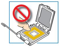
![]() When opening a socket, DO NOT TOUCH the gold socket wires.
When opening a socket, DO NOT TOUCH the gold socket wires.
![]() When unpacking a processor, hold by the edges only to avoid touching the gold contacts
When unpacking a processor, hold by the edges only to avoid touching the gold contacts
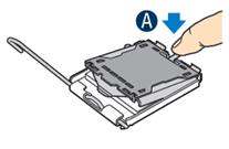
Open the socket lever
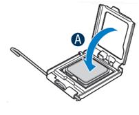
Open the load plate
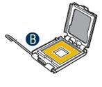
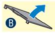
Remove the processor protective cover
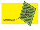
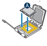
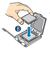
Install the processor
![]() CAUTION: The underside of the processor has components that may damage the socket pins if installed improperly. Processor must align correctly with socket opening before installation. DO NOT DROP processor into socket!
CAUTION: The underside of the processor has components that may damage the socket pins if installed improperly. Processor must align correctly with socket opening before installation. DO NOT DROP processor into socket!
Remove socket protective cover
Close load plate and socket lever
Install active heat sink
An active heat sink is required for the Intel® Entry Server Chassis SC5299-E. A typical active heat sink is shown as below. Rotate the active heat sink so that the power connector can reach the CPU fan header on the server board.
![]() CAUTION: The heat sink has thermal interface material (TIM) on the underside of it. Use caution so that you do not damage the thermal interface material. Use gloves to avoid sharp edges.
CAUTION: The heat sink has thermal interface material (TIM) on the underside of it. Use caution so that you do not damage the thermal interface material. Use gloves to avoid sharp edges.
Use the following procedure to install an active heat sink to your server board:
Repeat this procedure for each fastener.
Install memory DIMMs
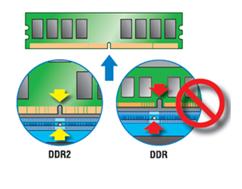
DDR2 DIMM memory identification:
![]() This server board supports up to four DDR2-667 or DDR2-800 ECC or non-ECC unbuffered DIMMs. DDR DIMMs are not supported on this server board.
This server board supports up to four DDR2-667 or DDR2-800 ECC or non-ECC unbuffered DIMMs. DDR DIMMs are not supported on this server board.
![]() DDR2 memory varies in height. DO NOT MIX different DIMM heights and types.
DDR2 memory varies in height. DO NOT MIX different DIMM heights and types.
DIMM notch and socket bump must align as shown.
Memory configurations and population order:
Memory Type: Minimum of one 512MB, DDR2 667/800 MHz compliant 240-pin DIMM.
Populate DDR2 DIMMs in the order of A1, B1 [blue sockets], then A2 and B2 [black sockets].
DIMMs must be identical with respect to size, speed, and organization.
| Note | For additional memory configurations, see the User’s Guide on the CD that accompanied your Intel® Server Board S3200SHV / S3210SHLC. |
Memory sizing and configuration is supported only for qualified DIMMs approved by Intel®.
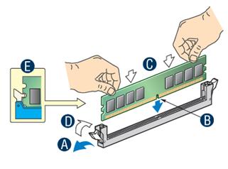
To install DIMMs:
![]() CAUTION: Avoid touching contacts when handling or installing DIMMs.
CAUTION: Avoid touching contacts when handling or installing DIMMs.
Make server board power connections
![]() CAUTION: Note the location of the latch on each power cable connector and align it with the matching tab on each server board socket.
CAUTION: Note the location of the latch on each power cable connector and align it with the matching tab on each server board socket.
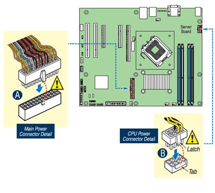
| Note | If you are using a non-Intel server chassis with an ATX power supply, see the documentation that came with your chassis for installation information. |
Install floppy drive, optical drive (SATA or IDE), and hard drive(s)
See the documentation that came with your server chassis for drive installation.
For the Intel® Entry Server Chassis SC5299-E, see the Quick Start User’s Guide accompanying the chassis.
Connect drives/front panel connector/external USB to server board
Make the following cable connections to the server board as shown:
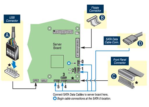
Chassis Fan Connections
For the Intel® Entry Server Chassis SC5299-E, see the Quick Start User’s Guide accompanying the chassis for specific system fan connection requirements.
For a non-Intel server chassis, see the “Making Connections…Quick Reference” section below, and the documentation accompanying your chassis for specific chassis fan connection requirements.
| Note | Return to your Intel® Server Chassis Quick Start User’s Guide, or your non-Intel chassis documentation to finish installation and configuration of your Intel® Server S3200SH / S3210SH. |
Return to this document to finish up, including software, BIOS, drivers and operating system installation.
Finishing up
Before installing your operating system, you must finish your chassis installation, make I/O connections and plug in AC power.
Software – BIOS, drivers, and operating system installation
If new versions are available, update the BIOS on your server. See the User Guide on the Intel® Server Deployment Toolkit 2.0 CD for update instructions.
Reference
| Intel® Entry Server Chassis SC5299-E with fixed 420W power supply | SC5299UP |
| Intel® Entry Server Chassis SC5299-E with fixed 420W power supply and North American power cord | SC5299UPNA |
List of accessories and spares
Hardware components that have been tested with this system
The system does not boot or shown video at power-on.
The system sometimes works, but is exhibiting erratic behavior.
Making Connections to the Server Board - Quick Reference
Required Connections for Selected Chassis SC5299-E
| C +12V CPU Power Connector |  |
| F Main Power Connector | |
| J Front Panel Connector | |
= Make this connection
CPU/System Fan Connections for Selected Chassis SC5299-E
| A CPU 1 Fan Connector |  |
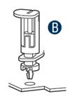
| B System Fan 1 Connector | |
| D System Fan 4 Connector | |
| E System Fan 3 Connector | |
| G System Fan 2 Connector |
= Make this connection
System Fan Connections: For a non-Intel server chassis, see the documentation that came with your chassis for fan connection requirements.
Optional Connections for Selected Chassis SC5299-E
| H Floppy Drive Connector | |
| I SATA Connectors | |
| K SATA Connectors | |
| L USB |
![]() = Make this connection
= Make this connection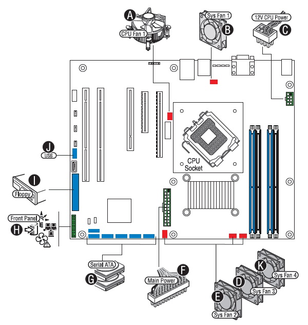
| Note | Not all optional connections are shown in this diagram. Refer to your Server Board User’s Guide, and your server chassis documentation for additional connection information. |
Intel® Server Board S3200SHV / S3210SHLC component layout
| A Not Available on the Intel® Server Board S3200SHV. B Not Available on the Intel® Server Board S3200SHV. C Intel® Adaptive Slot 6 functions as either a PCI Express* x16 (x8 lane) Connector or a Riser Card Slot in a 1U Chassis for S3210SHLC; PCI Express x16 Connector (x8 lane) for S3200SHV. D Not Available on the Intel® Server Board S3200SHV. |
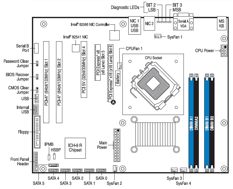
| Note | Not all components, jumpers and connectors are described in this diagram. Refer to your Server Board User’s Guide on the Intel® Server Deployment Toolkit 2.0 CD for additional information. |