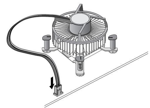
The following diagrams and instructions apply to the installation of LGA775-based Intel® Processors and the boxed fan-heatsink. Instructions assume that the fan-heatsink is new and has the factory applied thermal interface material applied to the bottom of the fan-heatsink.
If the process outlined below does not address your question, see the following below documents about the installation process:
Integration video
How to apply thermal interface material (TIM)
Resetting boxed processor fan-heatsink fasteners/pushpins
Your processor may or may not come with a processor cover. LGA775-based processors initially shipped with a processor cover. Later LGA775-based processors arrive in the plastic shipping case without the cover.
Installation process
- Open the socket lever by pushing lever down and away from the socket (A). Lift the lever (B).
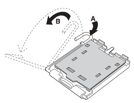
- Open the load plate (C). Do not touch the socket contacts (D).
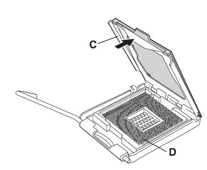
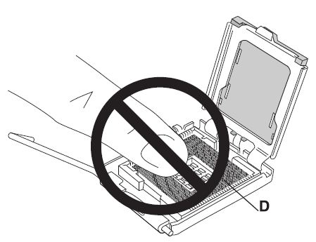
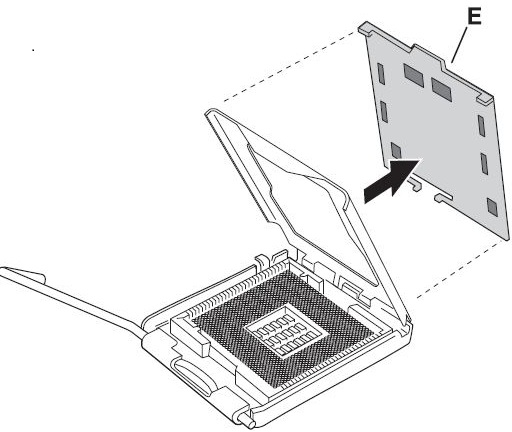
- Remove the protective cover (E) from the load plate. Do not discard the protective cover. Always replace the socket cover if the processor is removed from the socket.
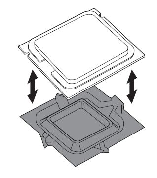
- Remove the processor from the protective cover. Hold the processor only at the edges. Do not touch the bottom of the processor. Do not discard the protective cover. Always replace the processor cover if the processor is removed from the socket.
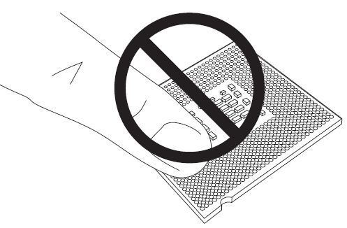
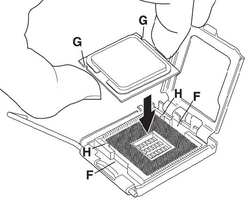
- Hold the processor with your thumb and index fingers, oriented as shown. Ensure your fingers align to the socket cutouts (F). Align the notches (G) with the socket (H). Lower the processor straight down without tilting or sliding the processor in the socket.
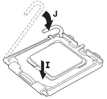
- Close the load plate. Press down on the load plate (I) to close and engage the socket lever (J).
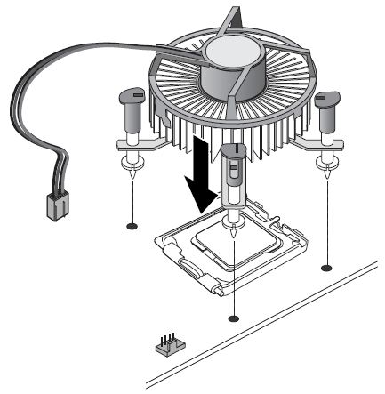
- With the motherboard installed in the chassis, place the fan-heatsink onto the motherboard. You must align the fasteners through the holes properly, or you risk damaging the bottom of the fasteners. Do not damage the thermal interface material (TIM) attached to the bottom of the fan-heatsink.
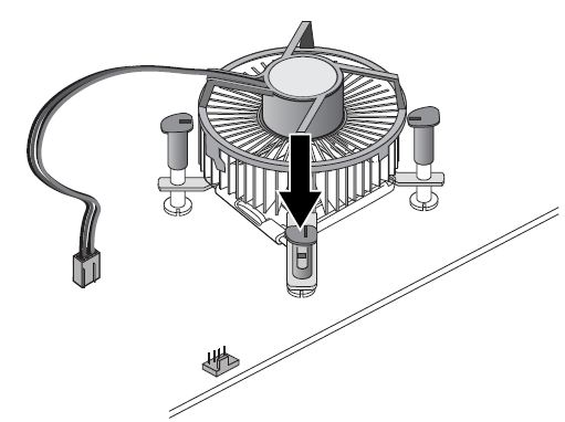
- Push down on the top of each fastener while holding the fan heat sink in place. You should hear a “click” when pushing down each fastener. Check that all four fasteners are securely attached by gently pulling up on each fastener. An unattached fastener prevents a good seal between the fan-heatsink and processor and can result in unreliable processor operation.
- Connect the processor 4-wire fan cable connector to the motherboard 4-pin CPU fan header. (The processor 4-wire fan cable connector can be connected to a motherboard 3-pin CPU fan header if a 4-pin CPU fan header is unavailable.)
