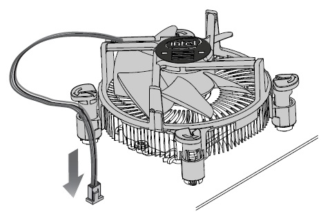
These instructions are applicable to boxed LGA1150/LGA1151/LGA1155/LGA1156/LGA1200 based processors and fan heat sinks because of the similarity of the installation process. Note that these processors are not compatible between the different sockets because of electrical, mechanical, and keying differences.
Visit Intel® Processor Installation Center for more information on integrating desktop processors.
These instructions assume that the boxed processor and fan heat sink are new and the factory-applied thermal interface material is applied to the bottom of the fan heat sink.
At the bottom of this page, there are links to installation documents for some of the sockets. These documents include information on how to reset the fan heat sink push-pins, how to reapply thermal interface material, and a link to the installation video.
Before you start: This processor is intended to be professionally installed. Take proper electrostatic discharge (ESD) precautions such as using appropriate ground straps, gloves, and ESD mats
-
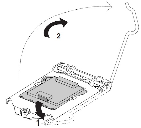
Push the lever down to unclip it (1) and lift it (2).
-
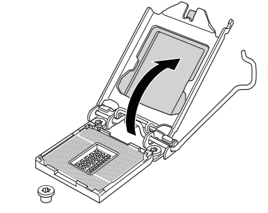
Open load plate.
-
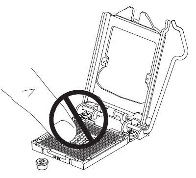
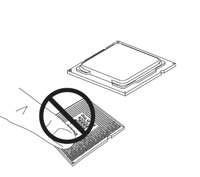
Do not touch the socket contacts or the bottom of the processor
-
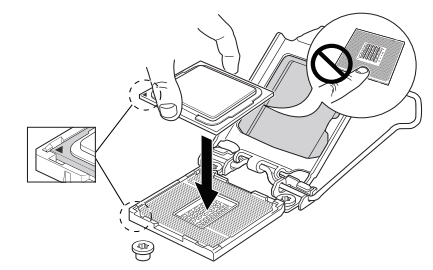
Hold the processor with your thumb and index fingers. Make sure socket pin 1 aligns with the processor pin 1. Also make sure that the socket notches align with the processor notches. Lower the processor straight down, without tilting or sliding the processor in the socket. Gently release the processor, making sure that it is seated correctly in the socket.
-
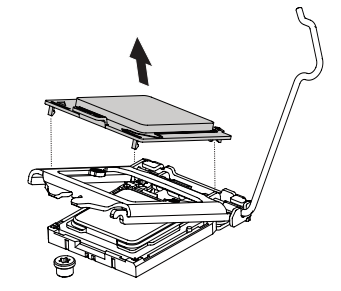
Open the load plate. Remove the protective cover from the load plate. Do not discard the protective cover. Always replace the socket cover if the processor is removed from the socket.
-
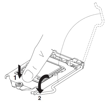
Very little force is required to close the load plate. Press down on the load plate, close, and engage the socket lever.
-
With the motherboard installed in the chassis, put the fan heat sink on the motherboard, aligning the fasteners through the holes. Align the fasteners through the holes properly, or you risk damaging the bottom of the fasteners. Also be careful not to damage the thermal interface material attached to the bottom of the fan heat sink.
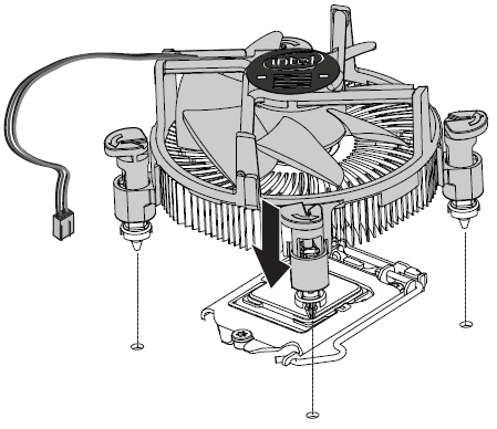
-
Push down on the top of each of the fasteners in an alternate pattern, as shown below, while holding the fan heat sink in place. You should hear a “click” when pushing down each fastener. Gently pull up on each fastener to make sure all four fasteners are securely attached. An unattached fastener prevents a good seal between the fan heat sink and processor, and can result in unreliable operation of the processor.
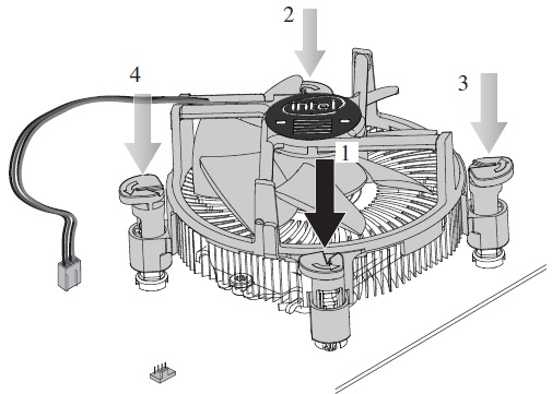
-
Connect the processor 4-wire fan cable connector to the motherboard 4-pin CPU fan header. (The processor 4-wire fan cable connector can be connected to a motherboard 3-pin CPU fan header if a 4-pin CPU fan header is unavailable.)
