Visible to Intel only — GUID: hco1423077190482
Ixiasoft
Visible to Intel only — GUID: hco1423077190482
Ixiasoft
14.5.5. Synthesis Information (SynthesisInfo)
The inputs and outputs to this subsystem become the primary inputs and outputs of the RTL entity that DSP Builder creates.
The SynthesisInfo block can be at the same level as the Device block (if the synthesizable subsystem is the same as the generated hardware subsystem). However, it is often convenient to create a separate subsystem level that contains the Device block. Refer to the design examples for some examples of design hierarchy.

| Parameter | Description |
|---|---|
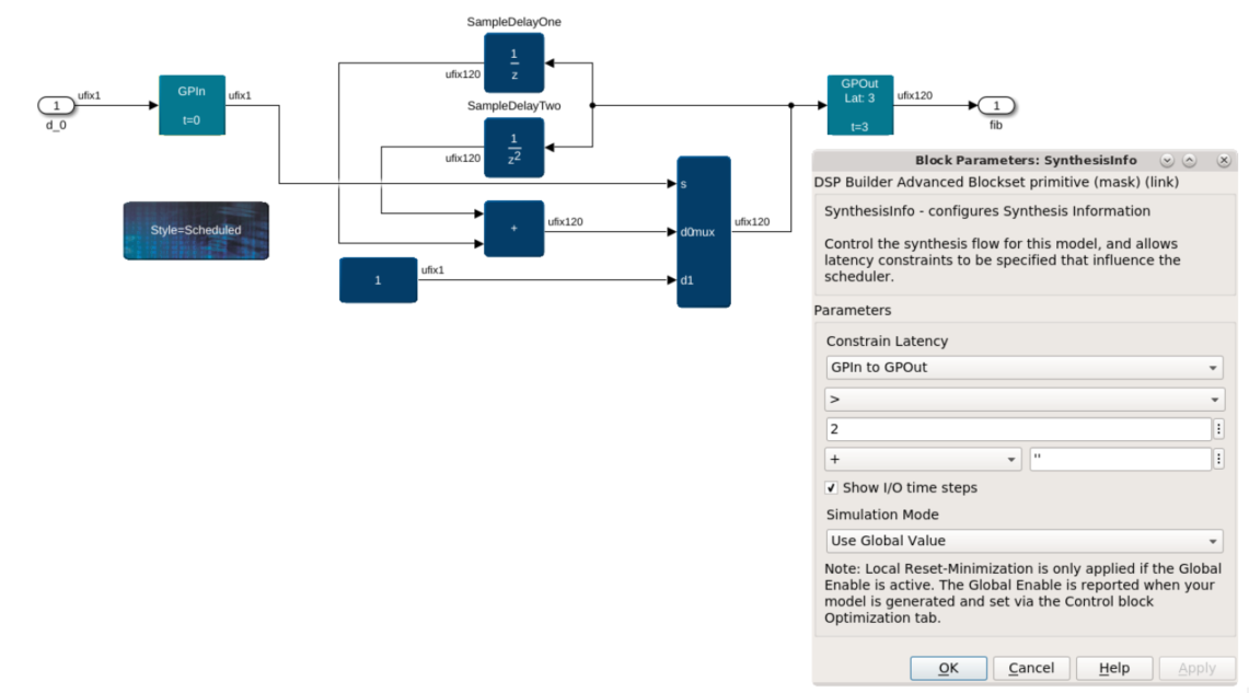
| Constrain Latency | Select the block types to which DSP Builder applies the latency constraint: Channel-In to Channel-Out or GPIn-to-GPOut. You can select the type of constraint and specify its value. The value can be a workspace variable or an expression but must evaluate to a positive integer. You can select the following types of constraint:
Select either + or - and enter an expression (refer to Dependent Latency Expressions). Constrain Latency only applies to subsystems which use the ChannelIn or ChannelOut blocks and not to subsystems that use the GPIn or GPOut blocks. |
| Show I/O time steps | Turn on to display the datapath's pipeline time steps on the block mask of the GPIn, GPOut, ChannelIn and ChannelOut blocks in your design. Time steps, in clock cycles, are the delay from an arbitrary reference point (usually the start of the datapath) to the given point in the pipeline. |
| Simulation mode | Select a trade-off between simulation speed and simulation accuracy with one of the four options:
|
| Local reset minimization | Select the reset minimization for the associated synthesizable subsystem. Valid only if Control block Global Enable is On. The default is Conditional – On for ChannelIn/Out only. Select Off to disable reset minimization on this synthesizable subsystem. Select On – Always (for ChannelIn/Out or GPIn/Out to apply reset minimization to a synthesizable subsystem that uses GPIn/Out blocks. In a GPIn/Out subsystem with reset minimization, the whole subsystem is data flow and has no valid signal to be control flow. |
The SynthesisInfo block has no inputs or outputs.
- Scheduled Synthesis
The Scheduled style of operation uses a pipelining and delay distribution algorithm that creates fast hardware implementations from an easily described untimed block diagram. This style takes full advantage of the automatic pipelining capability. - Updated Help
After you run a simulation, DSP Builder updates the help pages with specific information about each instance of a block. This updated help overrides the default help link. To find the updated help, click on the help link on the block after simulation. This updated help includes a link back to the help for the general block and the following information about the generated instance: